


Chapter 6 91
Configuring a LAN Node
Configure a LAN Network Interface
Configure a LAN Network Interface
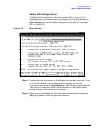
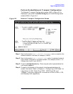
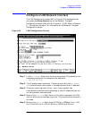
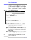
The LAN Configuration screen (#41) in Figure 6-2 is displayed when
you press the
[Config Network] key at the Network Transport
Configuration screen (#42) with an NI type of 1 (LAN). Refer to Chapter
5 , “Introductory Screens,” for information on the Network Transport
Configuration screen.
Figure 6-2 LAN Configuration Screen
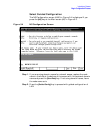
Step 1. In the IP address field, enter the internet protocol (IP) address for the
node being configured. An example of an address is:
C 192.191.191 009.
Step 2. The IP subnet mask is optional. If entering one, tab to the IP subnet
mask field and enter the number in the same format as an IP address.
Step 3. The proxy node is optional. Enter Y only if your network has
internetworks (networks with gateways) or non-HP nodes and you are
not using domain name services.
Step 4. Move to the Link name field. Enter a link name to represent the LAN
card for which you are configuring a link. This name must be unique to
the node.
Step 5. Move to the Link type field. Enter BT100 for a 100Base-T link, LAN
for a ThinLAN link, or VG100 LAN for a 100VG-AnyLAN link.