


Chapter 2 29
Networking Concepts
Subnetworks
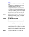
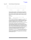
Figure 2-2 Class C Address with Subnet Number
Now, refer again to example 1. The subnet mask must indicate that
three bits of the node portion of the IP address will be used for the
subnet identifier. The subnet mask turns on (sets to 1) all the relevant
bits for its subnet scheme. The subnet mask for example 1 is shown
below. Note that the most significant three bits of the rightmost byte
are set.
Subnet Mask
Binary 11111111.11111111.11111111 11100000
Decimal 255.255.255 224
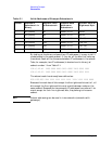
Table 2-1 shows valid addresses for the subnetwork in example 1. You
will need to know this information for NMMGR configuration. The
table shows the possible values of the rightmost byte of the IP address
for each of the subnets, given the criteria described in the example.
(Remember, an address of all 0s or all 1s is not valid).
Column 2 shows the values, in binary, of the six subnet addresses. Five
zeroes are shown in parentheses to indicate where the three
subnet-address bits are located in the byte. The equivalent decimal
value for each subnet address is shown in the third column. The fourth
column shows the range of possible values for the node address of each
subnet. The five rightmost bits make up the node portion, and the
range is the same for all subnets. By combining the subnet address with
the range of node addresses, the possible decimal values of the
rightmost byte are obtained and shown in the fifth column.
The table shows that subnets of 30 nodes each are possible given a
subnet mask of 255.255.255 224. This is derived from the column that
shows the range of possible values for the five bits that make up the
node portion of the IP address. The range for each of the six subnets
shows 30 possible values.