


44 Chapter3
Planning Your Network
Drawing an Internetwork Map
Drawing an Internetwork Map
This section deals with the internetwork as a whole. The internetwork
worksheets consist of an internetwork map, which shows an overview of
your internetwork, and an internetwork table. You will take the
following steps when filling out the internetwork worksheets:
• Draw sketches of each network in the internetwork.
• Write network names, IP network addresses, and network types.
• Draw gateway nodes.
• Indicate network boundaries.
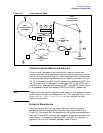
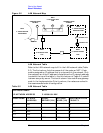
An internetwork map provides information about the whole
internetwork. Figure 3-1 is an example of an internetwork map. This
sample internetwork will be used throughout the instructions in this
chapter to help explain the other drawings and tables that make up the
configuration worksheets.
Before you can draw your internetwork map, you must know how many
networks your internetwork will contain, and you must know each
network type (ThinLAN, Token Ring, FDDI, 100VG-AnyLAN,
100Base-T, NS Point-to-Point, or X.25). The internetwork in the
example (Figure 3-1) contains six networks. NET1 and NET5 are LANs,
NET1 is 100Base-T LAN and NET5 is a ThinLAN, NET2 is a
Point-to-Point network, NET3 is an X.25 network, NET4 is a Token
Ring network, and NET6 is an FDDI network.
NOTE
If you have an X.25 network, you should indicate the presence of each
Datacomm and Terminal Controller (DTC) in your internetwork map,
as shown in this example (Figure 3-1). Both the NS 3000/iX node and
the DTC must be specially configured for X.25 links.