


Chapter 3 45
Planning Your Network
Drawing an Internetwork Map
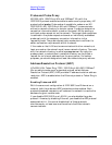
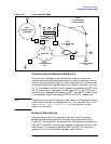
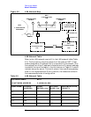
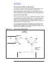
Figure 3-1 Internetwork Map
Communication Between Networks
Since the main purpose of the internetwork map is to show how
networks are connected, gateway nodes are the only nodes you should
label on the internetwork map. All other nodes and their networks can
be represented by drawing sketches of the networks, as shown in Figure
3-1. In the example, node B is a full gateway that belongs to NET1 and
NET2, node A is a full gateway that belongs to NET1 and NET4, and
node C is a full gateway that belongs to NET1 and NET6. Nodes G and
H are gateway halves that belong to NET2 and NET5, respectively.
NOTE
Single letters are used to represent node names in this example. Actual
node names must be in an accepted format. They may be either in the
form nodename.domain.organization or they may be in a valid
domain name format.
Network Boundaries
Once you have drawn your gateway nodes and routers, you have
established network boundaries. Consider the example and look at
Figure 3-1. Since node B in the example is a full gateway and belongs to
both NET1 and NET2, the boundary between these two networks is at
node B itself. The boundary between NET2 and NET5 is along the
gateway-half link that connects gateway nodes G and H.
K
B
DTC
DTC
DTC
NET4
C 192.004.002XXX
TOKEN RING
NET2
C 192.002.250XXX
POINT-TO-POINT
NET1
C 192.001.001XXX
LAN
NET6
C 192.006.003XXX
FDDI
NET3
C 192.003.251XXX
X.25
NET5
C 192.005.252XXX
LAN
Router
A
C
Router
X.25 PSN
H
I
J
G
N1
N2 N3
N5
L