


Chapter 7 119
Configuring a Point-to-Point Node
Configure Node Mapping
Configure Shared Dial Node Mapping
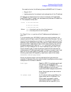
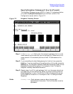
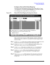
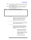
The Shared Dial Node Mapping Configuration screen (#46) in Figure
7-5is displayed if you press the
[Link Routing] key at the Point-to-Point
Link Configuration screen (#44) for a link of type SD.
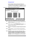
Figure 7-5 Shared Dial Node Mapping Configuration Screen
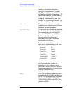
Each router NI can have up to 1024 mappings. However, 4096 is the
absolute maximum number of unique phone numbers supported per
NMCONFIG File.
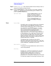
Step 1. In the Route Name field, enter a symbolic name that represents a route
between the node you are configuring and destination node
Step 2. In the Destination IP Address field, enter the IP address of the
destination node for which a route is being specified.
Step 3. In the Priority field, enter a number from 1 to 99 to indicate the
priority of this route if there are multiple routes to a destination.
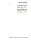
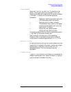
Step 4. In the Phone Number field, enter the telephone number of the
destination node. (Leave this field blank if the target node is
non-adjacent.)
Step 5. The Security String field is optional. You may enter a string that
remote nodes must use to gain dial link access to the node you are
configuring.