


Intermate100 and Intermate101 Print Server Administration Manual 229
Technical Information: Hardware
Appendix B. Technical Information
B.1. Hardware
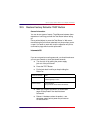
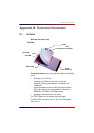
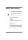
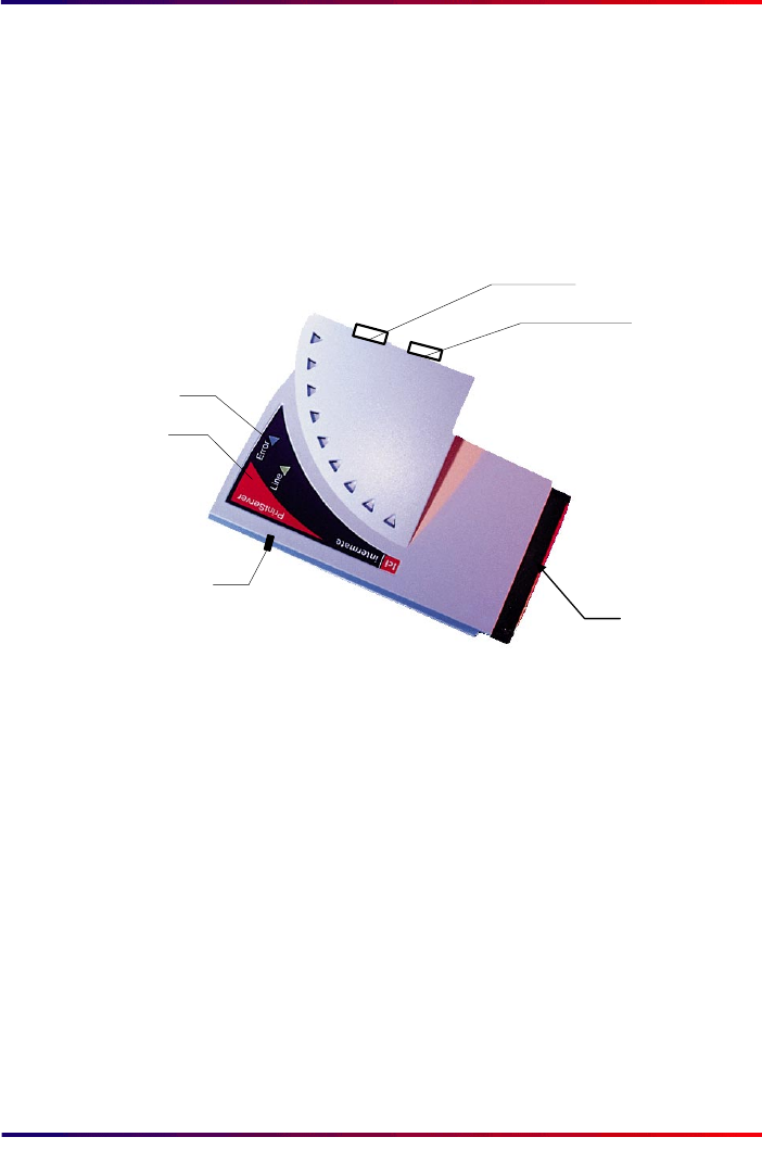
What the Unit Looks Like
The three outlets shown on the right hand side of the drawing
are for
• DC power: 6.5 V, 750 mA
• attaching to an Ethernet LAN: this is an RJ-45
connector including auto detection of 10BaseT and
100BaseTX.
In units sold before 4 January 2002 (up to and including
G22_1491) there is also auto detection of Ethernet II,
IEEE802.2, IEEE 802.3 and SNAP frames.
• attaching to the parallel port of a printer
The TEST Button can not be seen from this angle.
The Error LED is red when it is on. The Line LED is green
when it is on.
Error LED
Line LED
TEST button
power
printer
connector
LAN
connector
Top View