


Installation and operation precautions
1
C250P 1-36
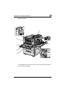
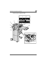
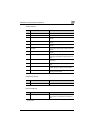
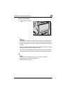
Finisher FS-514
Output tray OT-601
Punch kit PK-510
* Parts marked with an asterisk (*) are installed within the finisher and therefore are not shown in
the illustration.
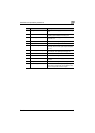
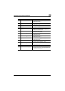
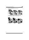
No. Part name Description
1 Output tray 1 Collects prints that are fed out
2 Output tray 2 Collects prints that are fed out
3 Dial [FN6] Turned when clearing paper misfeeds within the
finisher
4 Dial [FN5] Turned when clearing paper misfeeds within the
finisher
5 Dial [FN4] Turned when clearing paper misfeeds within the
finisher
6 Dial [FN2] Turned when clearing paper misfeeds within the
finisher
7 Lever [FN1] Raised when clearing paper misfeeds within the
finisher
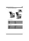
8 Hole-punch waste container Removed when emptying hole-punch waste
that has accumulated from using the punch set-
tings
9 Lever [FN3] Lowered when clearing paper misfeeds within
the finisher
10 Stapler Moved to the front when clearing jammed sta-
ples
11 Staple cartridge holder Removed from the stapler when replacing the
staple cartridge or clearing jammed staples
12 Dial Turned to move the stapler to the front when
clearing jammed staples
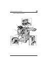
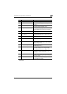
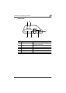
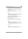
No. Part name Description
13 Optional output tray Collects prints
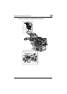
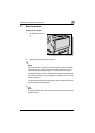
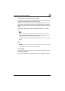
No. Part name Description
14 Punch Kit* Punches holes for filing printed pages when
punch kit PK-510 is installed onto finisher FS-
514