


Chapter 3 Removal and Replacement Procedures
3-149
Removal
1) Pull out the CASSETTE from the printer.
2) Remove the COVER TOP MAIN. (RRP1.4)
3) Remove the COVER SIDE L. (RRP1.14)
4) Remove the COVER SIDE R. (RRP1.9)
5) Remove the CHUTE ASSY TURN. (RRP3.1)
6) Remove the COVER CASSETTE REAR. (RRP3.2)
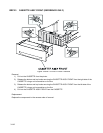
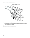
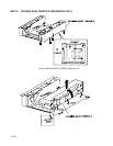
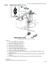
7) Deflect the shaft of the LINK ACTUATOR (PL3.3.5) secured to the ACTUATOR NO PAPER (PL3.3.4)
from the printer FEEDER and shift the ACTUATOR NO PAPER from the shaft.
8) Pull out the LINK ACTUATOR from the hole on the printer FEEDER and remove.
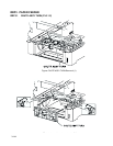
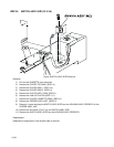
9) Remove the connector (P/J24) connecting the printer and FEEDER ASSY UNIT from the left side of
the printer.
10) Remove the connector (P/J210) connecting the printer and FEEDER ASSY UNIT from the right side of
the printer.
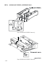
11) Remove the connector (P/J47) on the PWBA HNB DRV (PL12.1.12) from the right side of the printer.
12) Remove 8 screws securing the FEEDER ASSY UNIT to the printer.
In the following step, removal of the left front screw is blocked by the printer housing.
Lift the left front side of the printer up slightly to remove the screw.
13) Remove 4 long screws securing the FEEDER ASSY UNIT to the printer.
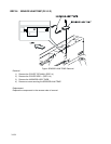
14) Shift the harness of the connector (P/J24) from the square hole on the bottom plate at the lower part of
the printer toward the FEEDER.
15) Shift the connector (P/J210) and the harness of the connector (P/J47) from the square hole on the bot-
tom plate at the lower part of the printer toward the FEEDER.
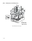
The top unit of the printer should be lifted up by more than one person.
When removing the top unit of the printer from the FEEDER ASSY UNIT, be careful not
to drop or damage the upper parts of the printer.
16) Raise the printer and separate it from the FEEDER ASSY UNIT.
Replacement
Replace the components in the reverse order of removal.
Take care not to pinch the harness on the FEEDER ASSY UNIT side, when replacing
the printer top unit on the FEEDER ASSY UNIT.