


Chapter 7 Wiring Diagrams and Signal Information
7-371
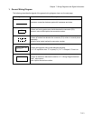
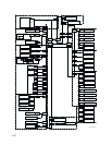
1. General Wiring Diagram
The following describes the legend of the general wiring diagram shown on the next page.
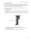
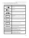
Symbols Description
Denotes a connection between parts with harnesses and wires.
A frame not having parts name inside denotes the connector (P/J).
Numeric value inside implies the connector number.
A frame of broken line denotes the connector (P/J) written in several places
separately.
Numeric value inside implies the connector number.
A frame having parts name inside denotes the parts.
PL X.Y.Z implies the item "Z" of plate (PL) "X.Y" in Chapter 5. Parts List.
A frame of dotted line denotes the section in "2. Wiring Diagram between
Parts", and numeric
value implies the section number.
XX
XX
PWBA HNB DRV
PL X.Y.Z
1