Chapter 3 Removal and Replacement Procedures
3-185
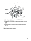
RRP5.2 SENSOR ADC ASSY (PL5.1.11)
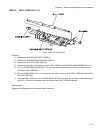
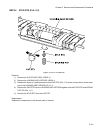
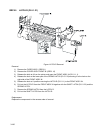
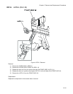
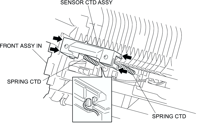
Figure: SENSOR ADC ASSY Removal
Removal
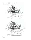
1) Release the latch at A from the printer and open the FRONT ASSY IN (PL5.1.1).
2) Remove the BTR UNIT ASSY. (RRP8.4)
3) Release the hooks at 4 positions securing the SENSOR ADC ASSY to the FRONT ASSY IN of the
printer.
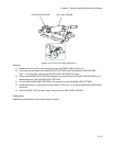
4) Raise the SENSOR ADC ASSY slightly from the FRONT ASSY IN and pull out the connector
(P/J136).
5) Remove the SENSOR ADC ASSY from the FRONT ASSY IN together with the SPRING ADC
(PL5.1.12).
6) Remove the SPRING ADC from the SENSOR ADC ASSY.
Replacement
Replace the components in the reverse order of removal.


