


Chapter 3 Removal and Replacement Procedures
3-239
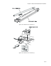
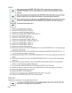
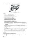
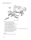
RRP10.4 HOLDER TCRU ASSY (3) (PL10.1.3)
Figure: HOLDER TCRU ASSY (3) Removal
Removal
1) Remove the FUSER ASSY. (RRP8.1)
2) Remove the BTR UNIT ASSY. (RRP8.4)
3) Remove the COVER TOP MAIN. (RRP1.4)
4) Remove the COVER ASSY FRONT HEAD. (RRP1.2)
5) Remove the COVER MSI. (RRP1.11)
6) Remove the TRAY ASSY MSI. (RRP1.12)
7) Remove the COVER ASSY FRONT. (RRP1.13)
8) Remove the COVER ASSY FRONT IN. (RRP1.10)
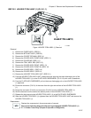
9) Remove the COVER SIDE L. (RRP1.14)
10) Remove the COVER SIDE R. (RRP1.9)
11) Remove the HOLDER TCRU ASSY UNIT. (RRP10.1)
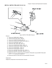
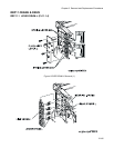
12) From the HOLDER TCRU ASSY UNIT, release the hook securing the toner discharging unit of the
HOLDER TCRU ASSY (3) on the PLATE ASSY DISPENSER L (PL10.1.9) with a mini screwdriver.
13) From the PLATE ASSY DISPENSER, pull out the toner discharging unit on the HOLDER TCRU ASSY
(3) rightward.
14) Release the hook securing the HOLDER TCRU ASSY (3) to the PLATE ASSY DISPENSER.
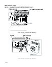
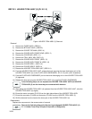
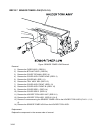
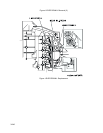
In the following steps, do not separate the HOLDER TCRU ASSY UNIT and HOLDER
TCRU ASSY (3) too far since they are connected with harness.
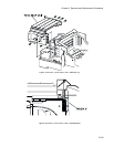
15) After sliding the HOLDER TCRU ASSY (3) rightward from the HOLDER TCRU ASSY UNIT, raise the
HOLDER TCRU ASSY (3) slightly.
16) Extract the motor connector (P/J513) from the right side surface of the HOLDER TCRU ASSY.
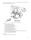
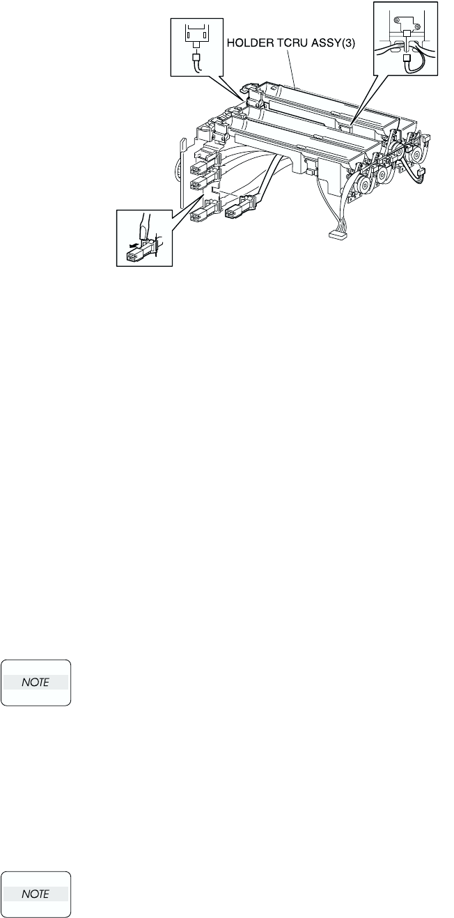
17) Extract the connector (P/J443) and connector (P/J433) from the HOLDER TCRU ASSY (3).
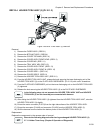
18) Shift the harness from the hook at the bottom portion of the HOLDER TCRU ASSY (3).
Replacement
Replace the components in the reverse order of removal.
Execute the following diagnosis after having exchanged HOLDER TCRU ASSY (3)
.
2.7.11 Holder Toner Assy (Chapter 2 Operation of Diagnostic)