


Chapter 3 Removal and Replacement Procedures
3-265
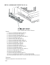
Removal
1) Remove the CONTROLLER BOARD. (RRP12.3)
2) Remove the CHUTE ASSY REGI. (RRP9.3)
3) Remove the COVER TOP MAIN. (RRP1.4)
4) Remove the COVER ASSY FRONT HEAD. (RRP1.2)
5) Remove the COVER MSI. (RRP1.11)
6) Remove the TRAY ASSY MSI. (RRP1.12)
7) Remove the COVER ASSY FRONT. (RRP1.13)
8) Remove the COVER ASSY FRONT IN. (RRP1.10)
9) Remove the COVER SIDE L. (RRP1.14)
10) Remove the HSG ASSY BIAS. (RRP9.2)
11) Remove the COVER SIDE R. (RRP1.9)
12) Remove the COVER ASSY TOP PHD. (RRP1.5)
13) Remove the COVER REAR. (RRP1.6)
14) Remove the HOLDER TCRU ASSY UNIT. (RRP10.1)
15) Remove the PWBA HNB DRV. (RRP12.6)
16) Remove the LVPS STD. (RRP12.4)
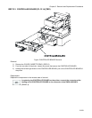
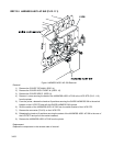
17) Remove the connector (P/J210) connecting the printer and FEEDER from the right side surface of the
printer.
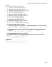
18) Remove the connector (P/J151) on the ROS ASSY (PL9.1.1) from the right side surface of the printer.
19) Remove the connector (P/J24) connecting the FEEDER to the printer from the left side surface of the
printer.
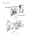
20) Remove the connector (P/J141), connector (P/J1361), connector (P/J138), connector (P/J221) and
connector (P/J139) on the connector bracket from the left side surface of the printer.
21) Remove the connector (P/J19) on the PWBA HNB MCU (PL12.1.1) from the inside of the printer.
22) Remove 1 screw securing the earth cable from the left side surface of the printer.
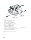
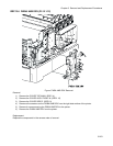
23) Remove 4 screws securing the BOX ASSY MCU/ESS to the printer.
24) Pull out the BOX ASSY MCU/ESS rearward from the printer and remove.
Replacement
Replace the components in the reverse order of removal.