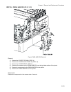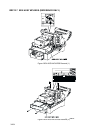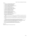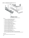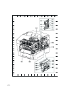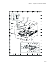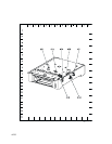
Chapter 4 Plug/Jack (P/J) Connector Locations
4-271
1. Connector [P (plug) / J (jack)]
1.1 List of P/J
P/J Coordiates Remarks
11 J-43 Connects PWBA HNB MCU and PWBA HNB DRV
12 I-43 Connects PWBA HNB MCU and PWBA HNB DRV
13 H-43
Connects PWBA HNB MCU, S-HVPS, FSR2(FSR22) Harness Assembly, Front 2
Harness Assembly and CTD Harness Assembly
14 J-43 Connects PWBA HNB MCU and Controller Board
15 H-43 Connects PWBA HNB MCU and ROS Assembly
18 H-44
Connects PWBA HNB MCU and REGI Chute Assembly (REGI Clutch, REGI
Sensor)
19 H-44 Connects PWBA HNB MCU and Retard Housing Assembly (TURN Clutch)
21 I-43 Connects PWBA HNB MCU and OPFREC Harness Assembly
22 J-43 Connects PWBA HNB MCU and OPEPANE BS Harness Assembly
23 I-43 Connects PWBA HNB MCU and LVPS STD Assembly
24 H-43 Connects PWBA HNB MCU and TMPA Harness Assembly
26 H-43 --
30 H-43 Flash-write
31 J-43 Test-print
32 H-43 Connects PWBA HNB MCU and OHP Sensor
41 I-18 Connects PWBA HNB DRV and PWBA HNB MCU
42 J-18 Connects PWBA HNB DRV and PWBA HNB MCU
47 J-18
Connects PWBA HNB DRV, Pick Up Assembly (No Paper Sensor, Low Paper
Sensor, Solenoid Feed, Clutch Assembly Turn) and Switch Assembly Size
48 I-18 Connects PWBA HNB DRV and Main Drive Assembly
49 I-17 Connects PWBA HNB DRV and DEVE Drive Assembly
50 J-18
Connects PWBA HNB DRV, Chute Assembly Exit (Motor Assembly DUP) and Cover
Assembly Front Head (Fan Fuser)
51 J-16
Connects PWBA HNB DRV and Holder TCRU Assembly (CRU Sensor, Low Toner
Sensor, TNR Motor)
52 I-18 Connects PWBA HNB DRV and Chute Assembly IN (Fuser Drive Assembly)
60 I-17 Connects PWBA HNB DRV and LVPS STD Assembly
61 J-18 Connects PWBA HNB DRV and LVPS STD Assembly
71 B-32 Connects EEPROM Harness Assembly and Plate Assembly Dispenser L (CONN
Assembly CRUM MC)
131 B-7 Connects Chute Assembly Exit (Motor Assembly DUP) and PWBA HNB DRV
132 B-9 Connects Chute Assembly Out (Solenoid Feed MSI) and Front 1A Harness
Assembly
133 D-8 Connects Chute Assembly Out (DUP JAM Sensor) and Front 1A Harness Assembly
134 D-6 Connects Chute Assembly Out (Full Stack Sensor) and Front 1A Harness Assembly
135 C-9 Connects Chute Assembly Out (MSI No Paper Sensor) and Front 1A Harness
Assembly
136 C-23 Connects Front Assembly In (ADC Sensor Assembly) and Front 1A Harness
Assembly
137 F-8 Connects Cover Assembly Front Head (Fan Fuser) and PWBA HNB DRV
138 B-32 Connects Front 1A Harness Assembly and Fuser Assembly
139 B-33 Connects Front 1A Harness Assembly and Chute Assembly Out (Solenoid Feed
MSI, DUP JAM Sensor, Full Stack Sensor, MSI No Paper Sensor)


