Chapter 6 Principles of Operation
6-361
7. Control
7.1 Control of Paper Size
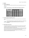
"ON/OFF of Paper Size Switch of SWITCH ASSY SIZE" and "Diag Tool indication data" are shown in the
table below.
Paper Size Switches are indicated as SW1, SW2, and SW3 from the above one.
7.2 Selective Control on Paper Pick-up Unit
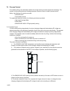
When not controlled by the printer controller, paper pick-up unit selected at the time of turning ON are as
follows.
The paper feeder by the paper tray under the printer is called "Tray 1", and the first tray
and the second tray in optional TRAY UNIT are called "Tray 2" and "Tray 3"
respectively.
7.3 ROS Light Quantity Control
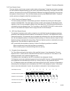
The image data are entered to the laser diodes in the ROS ASSY as electric signals (data are expressed
with high and low voltage values), and the laser diodes convert the image data from electric signals to
optical signals (data are expressed with blinking laser beams).
Variations in light quantity of laser beams or variations in optical system (such as lenses) or drum sensitivity
cannot attain proper electrostatic image, and accordingly the laser diodes monitor the light quantity of laser
beams to control the light quantity so as to attain stable and proper electrostatic image.
The ROS in this printer has four laser diodes for yellow, magenta, cyan, and black respectively, and the
light quantity is automatically adjusted for each color.
Paper Size
Paper Size Switch
Diag
indication data
SW1 SW2 SW3
LEGAL14" (SEF) ON ON ON 00
LEGAL13" (SEF) ON ON OFF 01
EXECUTIVE (SEF) ON OFF ON 02
B5 (SEF) ON OFF OFF 03
A4 (SEF) OFF ON ON 04
LETTER (SEF) OFF OFF ON 06
A5 OFF ON ON
No cassette OFF OFF OFF 07


