


Chapter 3 Removal and Replacement Procedures
3-211
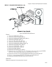
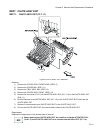
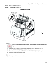
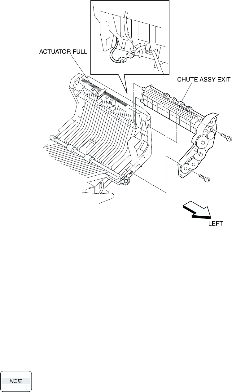
RRP7. CHUTE ASSY EXIT
RRP7.1 CHUTE ASSY EXIT (PL7.1.1)
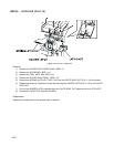
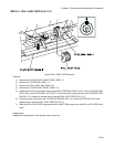
Figure: CHUTE ASSY EXIT Removal
Removal
1) Remove the COVER ASSY FRONT HEAD. (RRP1.2)
2) Remove the COVER MSI. (RRP1.11)
3) Remove the TRAY ASSY MSI. (RRP1.12)
4) Remove the COVER ASSY FRONT. (RRP1.13)
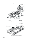
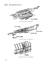
5) Remove the connector (P/J131) of the MOTOR ASSY DUP (PL7.1.8) on the CHUTE ASSY OUT
(PL6.1.1).
6) Shift the harness of the MOTOR ASSY DUP (PL7.1.8) to the CHUTE ASSY EXIT side from the
CHUTE ASSY OUT.
7) Remove 2 screws securing the CHUTE ASSY EXIT to the CHUTE ASSY OUT.
8) Pull out the CHUTE ASSY EXIT from the left side surface of the CHUTE ASSY OUT.
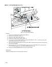
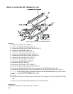
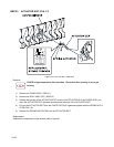
Replacement
Replace the components in the reverse order of removal.
When replacing the CHUTE ASSY EXIT, be careful to avoid the ACTUATOR FULL
(PL6.1.5) on the CHUTE ASSY OUT to be inserted into the ROLL EXIT (PL7.1.4).