


Chapter 3 Removal and Replacement Procedures
3-189
Removal
1) Remove the FUSER ASSY. (RRP8.1)
2) Remove the BTR UNIT ASSY. (RRP8.4)
3) Remove the COVER TOP MAIN. (RRP1.4)
4) Remove the COVER ASSY FRONT HEAD. (RRP1.2)
5) Remove the COVER MSI. (RRP1.11)
6) Remove the TRAY ASSY MSI. (RRP1.12)
7) Remove the COVER ASSY FRONT. (RRP1.13)
8) Remove the CHUTE ASSY EXIT. (RRP7.1)
9) Remove the COVER ASSY FRONT IN. (RRP1.10)
10) Remove the COVER SIDE L. (RRP1.14)
11) Remove the COVER SIDE R. (RRP1.9)
12) Remove the CHUTE ASSY OUT. (RRP6.1)
13) Remove the FRONT ASSY IN. (RRP5.1)
14) Remove the LATCH R. (RRP5.5)
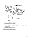
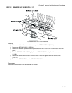
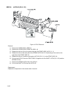
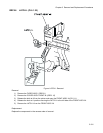
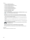
15) Remove a screw securing the earth (P/J233) of the HARNESS ASSY FSR (PL4.1.9) to the FUSER
DRIVE ASSY of the FRONT ASSY IN (PL5.1.1).
16) Remove a screw securing the edge (P/J235) of the WIRE ASSY FSR EARTH (PL5.1.20) to the MAIN
DRIVE ASSY (PL11.1.14).
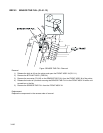
17) Shift the harness (P/J52) and earth (P/J235) of the FUSER DRIVE ASSY from the hook and housing,
secured to the FRONT ASSY IN (PL5.1.1).
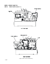
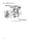
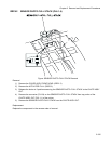
18) Remove 3 screws securing the FUSER DRIVE ASSY to the FRONT ASSY IN.
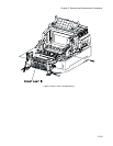
19) Remove the FUSER DRIVE ASSY from the FRONT ASSY IN.
Replacement
Replace the components in the reverse order of removal.