Chapter 3 Removal and Replacement Procedures
3-223
Replacement
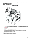
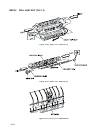
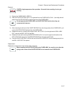
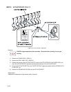
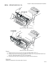
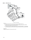
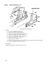
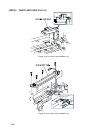
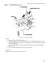
1) Align the ROS ASSY with its replace position to the printer.
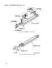
2) Secure the left and right shafts of the ROS ASSY to the printer with the hooks at the top of SPRING
ROS (PL9.1.2).
3) Secure the ROS ASSY to the printer with 1 screw.
4) Replace the connector (P/J151) to the ROS ASSY.
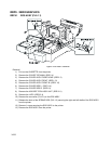
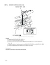
5) Replace the LVPS. (RRP12.4)
6) Replace the HOLDER TCRU ASSY UNIT. (RRP10.1)
7) Replace the COVER SIDE R. (RRP1.9)
8) Replace the COVER SIDE L. (RRP1.14)
9) Replace the COVER ASSY FRONT IN. (RRP1.10)
10) Replace the COVER ASSY FRONT. (RRP1.13)
11) Replace the COVER ASSY FRONT HEAD. (RRP1.2)
12) Replace the COVER TOP MAIN. (RRP1.4)
13) Replace the CASSETTE to the printer.


