R61509V Target Spec
Rev. 0.11 April 25, 2008, page 131 of 181
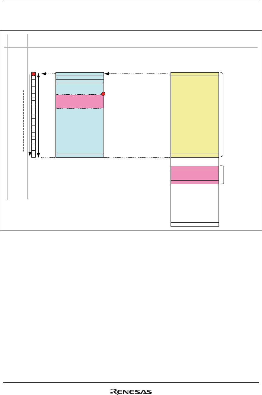
The following figure shows the relationship among the RAM address, display position, and the lines driven
for the display.
0
3
NL
9’h000
n-1
(
n line
)
NL
PTDP
1
PTSA
PTEA
9’h1AF
1
2
4
5
NL
Base image
RAM area
Partial image
RAM area
Partial image
Display area
LCD panel
physical line address
RAM line address
Display
data output
order
Display screen
0 (1st line)
1 (2nd line)
2 (3rd line)
Figure 51 Display RAM Address and Panel Display Position
Note: This figure shows the relationship between RAM line address and the display position on the panel.
In the R61509V’s internal operation, the data is written in the RAM area specified by the window
address setting.


