R61509V Target Spec
Rev. 0.11 April 25, 2008, page 53 of 181
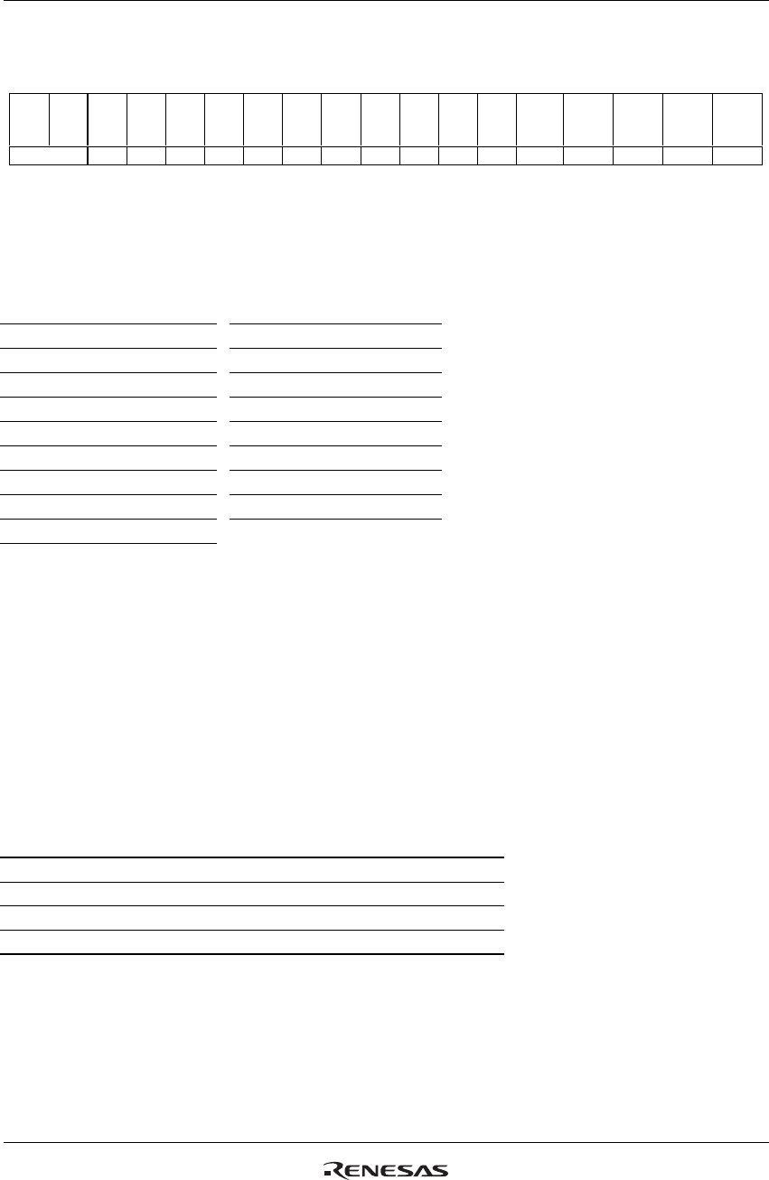
Panel Interface Control 1 (R010h)
RTNI[4:0]: Sets 1H (line) period. This setting is valid when the R61509V’s display operation is
synchronized with internal clock signal.
Table 22 Clocks per Line (Internal Clock Operation)
RTNI[4:0] Clocks per Line
RTNI[4:0] Clocks per Line
5’h00-5’h0F
Setting inhibited
5’h18 24 clocks
5’h10 16 clocks 5’h19 25 clocks
5’h11 17 clocks 5’h1A 26 clocks
5’h12 18 clocks 5’h1B 27 clocks
5’h13 19 clocks 5’h1C 28 clocks
5’h14 20 clocks 5’h1D 29 clocks
5’h15 21 clocks 5’h1E 30 clocks
5’h16 22 clocks 5’h1F 31 clocks
5’h17 23 clocks
Note: In Power Supply Instruction Setting, Deep Standby Exit Sequence and Sleep Mode Exit Sequence,
RTNI bit must be set at the “Initial instruction setting” state. See “Power Supply Setting Sequence”
and “Instruction Setting Sequence and Refresh Sequence”.
DIVI[1:0]: Sets the division ratio of the internal clock frequency. The R61509V’s internal operation is
synchronized with the frequency divided internal clock, which is set according to the division ratio
determined by DIVI[1:0] setting. The frame frequency can be changed by setting RTNI and DIVI bits.
When changing the number of lines to drive the LCD panel, adjust the frame frequency too. For details,
see Frame-Frequency Adjustment Function.
In RGB interface operation, the DIVI[1:0] setting has no effect.
Table 23 Division Ratio (Internal Operation)
DIVI[1:0] Division Ratio Internal Operation Clock Unit
2’h0 1/1 1 x OSC
2’h1 1/2 2 x OSC
2’h2 1/4 4 x OSC
2’h3 1/8 8 x OSC
Note: In Power Supply Instruction Setting, Deep Standby Exit Sequence and Sleep Mode Exit Sequence,
RTNI bit must be set at the “Initial instruction setting” state. See “Power Supply Setting Sequence”
and “Instruction Setting Sequence and Refresh Sequence”.
R/W RS IB15 IB14 IB13 IB12 IB11 IB10 IB9 IB8 IB7 IB6 IB5 IB4 IB3 IB2 IB1 IB0
R/W 1 0 0 0 0 0 0
DIV
I
[1]
DIV
I
[0]
0 0 0
RTNI
[4]
RTNI
[3]
RTNI
[2]
RTNI
[1]
RTNI
[0]
Default 0 0 0 0 0 0 0 0 0 0 0 1 1 0 0 1


