R61509V Target Spec
Rev. 0.11 April 25, 2008, page 135 of 181
Scan Mode Setting
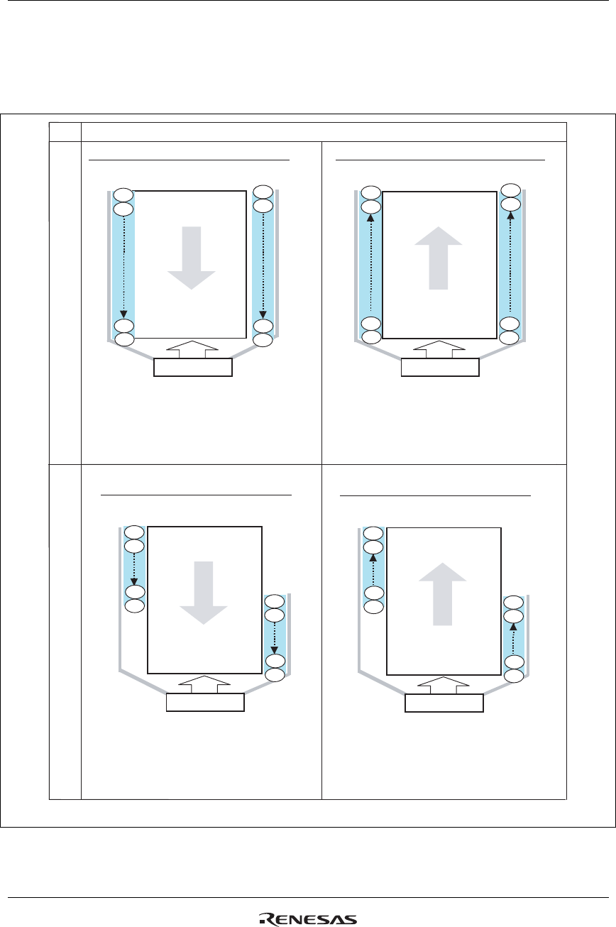
The R61509V can set the gate pin assignment and the scan direction in the following 4 different ways by
setting SM and GS bits to realize various connections between the R61509V and the LCD panel.
SM
Scan direction
0
Note: the numbers in the circles in the figure shows the order of scan.
G1ЈG2ЈG3ЈG4.... G429ЈG430ЈG431ЈG432
R61509V
432
430
2
main
Panel
176
431
429
1
(Non-bump view)
240
Interchanging forward direction (GS=0)
3
4
G4ЈG3ЈG2ЈG1....G432ЈG431ЈG430ЈG3429
R61509V
main
Panel
176
2
4
(Non-bump view)
240
432
Interchanging backward direction (GS=1)
432
430
Scan order (Gate line No.)
G4ЈG2ЈG431ЈG429 ....
G3ЈG1
G432ЈG430 ....
R61509V
1
2
216
main
Panel
(Non-bump view)
240
432
Left/right backward direction (GS=1)
215
217
218
432
431
1
Scan order (Gate line No.)
G2ЈG4....G1ЈG3.... G429ЈG431Ј
G430ЈG432
R61509V
432
431
217
main
Panel
(Non-bump view)
240
432
Left/right forward direction (GS=0)
218
216
215
1
2
Scan order (Gate line No.)
Scan order (Gate line No.)
1
3
431
429
(GS)
(GS)
(GS)
(GS)
Figure 55


