R61509V Target Spec
Rev. 0.11 April 25, 2008, page 165 of 181
Index Write
(
Data=8’h00
)
Index Write
(
Data=8’h00
)
Index Write
(
Data=8’h00
)
Index Write
(
Data=8’h00
)
Index Write
(
Data=8’h00
)
Index Write
(
Data=8’hFF
)
Index Write
(
Data=8’h00
)
Index Write
(
Data=8’h00
)
Index Write
(
Data=8’h00
)
Index Write
(
Data=8’h00
)
㩷
㩷
㩷 㩷
㩷
㩷
㩷
㩷
㩷
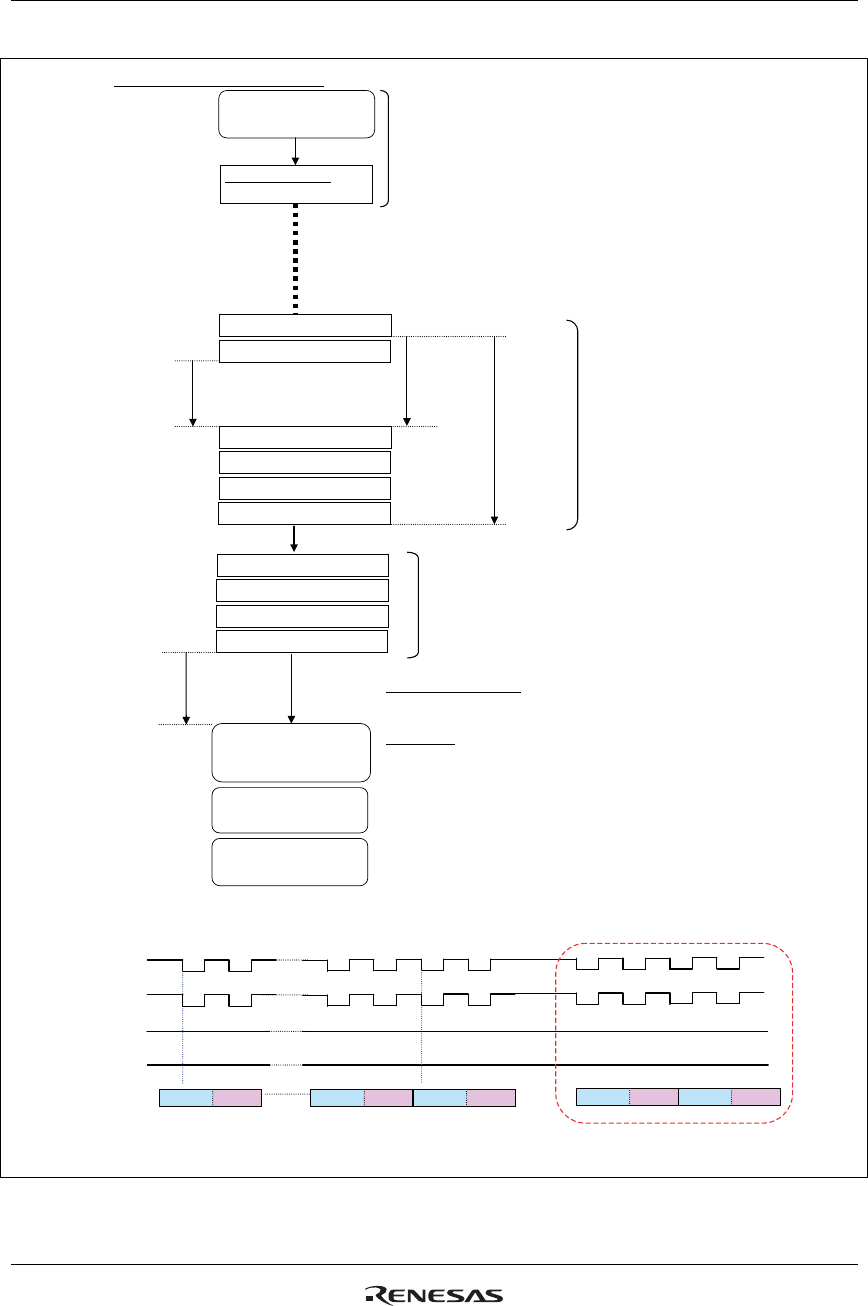
Notes: 1. See AC characteristics in Electrical Characteristics for details on low width (PWLW), high width (PWHW), and cycle (tCYCW) periods.
2. Leave at least 1 ms between the 2nd and 3rd Index write.
3. Set transfer synchronous command data 8'h00 when using 8 bit interface and 9'h000 when using 9-bit interface.
RAM data setting
Display ON sequence
Refresh sequence 2
VDD startup,
Oscillation startup period
Initialize the
R61509V.
Set shutdown mode
Display OFF sequence
Exit shutdown mode
(2) 9-/8-bit interface operation
0.3ms
or more
1ms
or more
Automatic NVM data load
RS
Data
“High”
“Low”
00h
00h
00h
00h
00h
FFh
00h 00h 00h
00h
Upper IW
Lower IW
Upper IW
Upper IW
Upper IW
Upper IW
Lower IW Lower IW
Lower IW
Lower IW
Set shutdown mode
R100h: DSTB=1
Transfer synchronization command (see note 3)
User setting
NL, BP, FP, γ control,
RTNI, DIVI, and others
Executing refresh sequence
regularly is recommended.
Transfer synchronization
1
2
3
4
5
6
1
2
3
4
Waveforms in Exiting Shutdown Mode (Input RS = “Low”and Index Write)
Wait
1ms.
Execute transfer synchronization command by inputting RS = “Low” and Index Write after exiting shutdown mode.
CSX
WRX
RDX
Figure 74


