R61509V Target Spec
Rev. 0.11 April 25, 2008, page 159 of 181
Power Supply Setting Sequence
The following are the sequences for setting power supply ON/OFF instructions. Set power supply ON/OFF
instructions according to the following sequences in Display ON/OFF, Sleep set/exit sequences.
㪭㪚㪚
㪠
㪦㪭㪚㪚
㪭㪚
㪠
㪞
㪥㪛
㩷
㩷
㩷
㩷
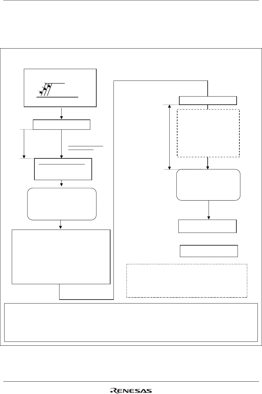
Power Supply ON Sequence
Notes: 1. Set VCMR to 1 when using internal electric volume.
2. When NVM is in the status that the R61509V is shipped out, set the instruction register (R280h: VCM[6:0], and
UID[7:0]). If writing values to VCM[6:0] and UID[7:0] has been completed, setting this instruction register is
unnecessary.
(A) Liquid crystal
power supply OFF
(DCDC OFF) state
Display OFF state
(B) Liquid crystal
power supply ON
(DCDC ON) state
Display OFF state
OR
R102h: PSON=1, PON=1
Power ON reset
Transfer synchronization
1ms
or more
Power supply (VCC, VCI, IOVCC) ON
VCC → IOVCC → VCI
or VCC, IOVCC, VCI simultaneously
Display ON sequence
NVM erase sequence
Instruction user setting
R400h: NL[5:0]
R008h: BP[7:0], FP[7:0]
R300h~R309h: γ control
R010h: RTNI[4:0], DIVI[1:0]
R100h: BT[2:0], AP[1:0]
R101h: VC[2:0], DC0[2:0], DC1[2:0]
Other user settings: see notes 1 and 2.
RS=0, DB=16’h0000
RS=0, DB=16’h0000
RS=0, DB=16’h0000
RS=0, DB=16’h0000
Power supply startup time
(6 frames x 1/osc)
(1) Other mode setting instruction
(2) RAM write instruction,
etc.
Automatic NVM data load
Access is prohibited
1ms after reset.
(1) To turn the display on, follow “Display ON Sequence”
in “Instruction Setting Sequence and Refresh Sequence”.
(2) To erase data from NVM, follow “NVM Erase Sequence”.
Erase data from NVM according to “NVM Control”.
Figure 69


