


R/C Operation
102 AX1500 Motor Controller User’s Manual Version 1.9b. June 1, 2007
Selecting the R/C Input Mode
The R/C Input Mode is the factory default setting.
If the controller has been previously set to a different Input Mode, it will be necessary to
reset it to the R/C mode using the serial port and the PC utility. See “Using the Roborun
Configuration Utility” on page 161, and “Accessing & Changing Configuration Parameter in
Flash” on page 133
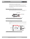
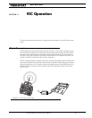
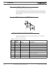
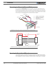
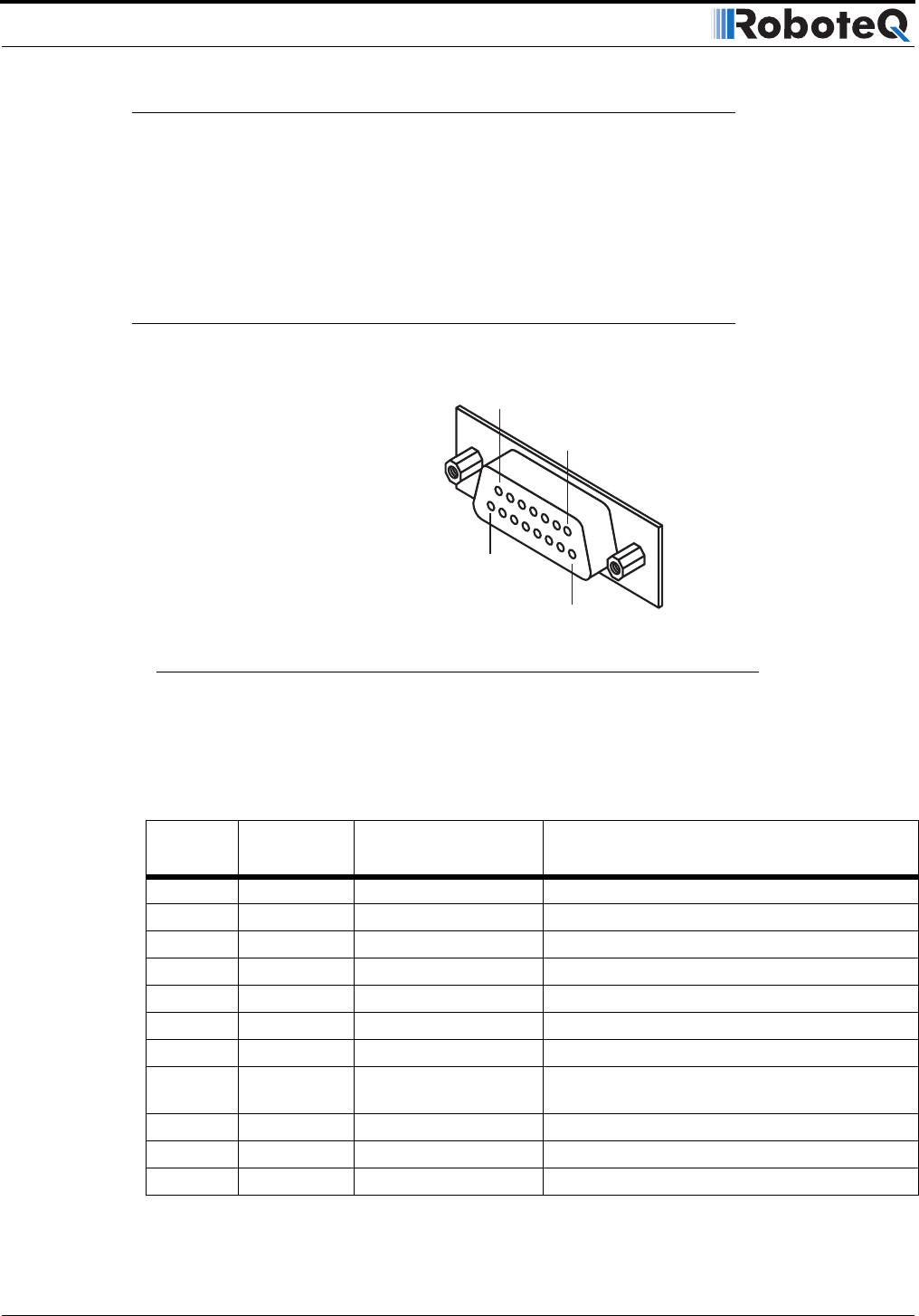
Connector I/O Pin Assignment (R/C Mode)
When used in R/C mode, the pins on the controller’s DB15 connector are mapped as
described in the table below.
TABLE 16. Connector pin-out in R/C mode
Pin
Number
Input or
Output Signal Description
1 and 9 Output Output C 2A Accessory Output C
2 Output RS232 data RS232 Data Logging Output
3 Input Ch 1 R/C radio Channel 1 pulses
4 Input Ch 2 R/C radio Channel 2 pulses
5 and 13 Power Out Ground Controller ground (-)
6 Unused Unused Unused
7 Unused Unused Unused
8 Digital In R/C: Ch 3 / Ana In 4 R/C radio Channel 3 pulses - (Not available when
encoder module present)
10 Analog in Ana in 2 Channel 2 speed or position feedback input
11 Analog in Ana in 1 Channel 1 speed or position feedback input
12 Analog in Ana in 3 Unused
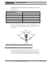
Pin1
8
15
9
FIGURE 62. Pin locations on the controller’s 15-pin connector