


Connecting Power and Motors to the Controller
30 AX1500 Motor Controller User’s Manual Version 1.9b. June 1, 2007
All 3 ground (-) are connected to each other inside the controller. The two main battery
wires are also connected to each other internally. However, you must never assume that
connecting one wire of a given battery potential will eliminate the need to connect the
other.
Controller Powering Schemes
Powering the Controller from a single Battery
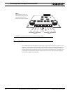
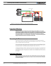
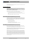
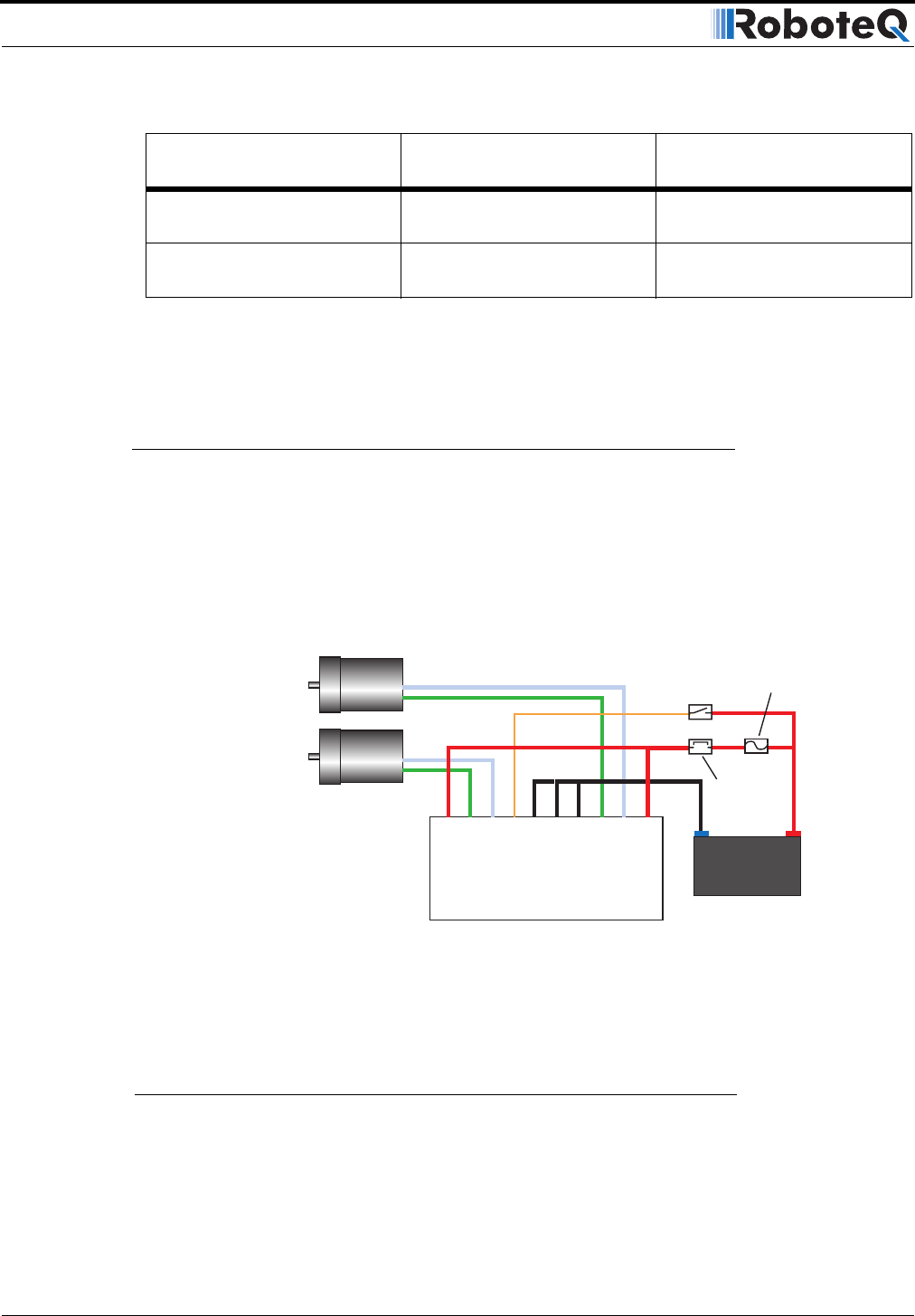
The diagram on Figure 11 show how to wire the controller to a single battery circuit and
how to turn power On and Off.
Connect two of the three Ground terminals to the minus (-) terminal of the battery that will
be used to power the motors. Connect the two VMot terminals to the plus (+) terminal of
the battery. The motor battery may be of 12 to 40 Volts.
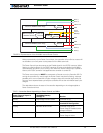
10.5V to 40V 0V Controller is On.
Power Stage is Off
10.5V to 40V 1V to 40V Controller is On.
Power Stage is Active
TABLE 2. Controller Status depending on Power Control and VMot
Power Control input is
connected to
And Main Battery
Voltage is Action
12V to 24V
Motor Battery
Power on/off
switch
Optional
Emergency
Disconnect
-
+
+
-
Motor1
Motor2
Controller
Fuse
VMot
VMot
M1+
M1-
VCon
GND
GND
GND
M2+
M2-
FIGURE 9. Powering the AX1500 from a single battery
Notes:
- The Battery Power connection are doubled in order to provide the maximum current to the controller. If
only one motor is used, only one set of motor power cables needs to be connected.
- Typically, 1, 2 or 3 x 12V batteries are connected in series to reach 12V, 24V or 36V respectively.