


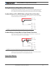

Closed Loop Position Mode
88 AX1500 Motor Controller User’s Manual Version 1.9b. June 1, 2007
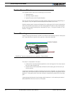
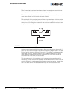
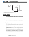
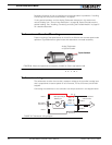
The diode polarity depends on the particular wiring and motor orientation used in the appli-
cation. If the diode is mounted backwards, the motor will not stop once the limit switch
lever is pressed. If this is the case, reverse the diode polarity.
The diodes may be eliminated, but then it will not be possible for the controller to move the
motor once either of the limit switches has been triggered.
The main benefit of this technique is its total independence on the controller’s electronics
and its ability to work in practically all circumstances. Its main limitation is that the switch
and diode must be capable of handling the current that flows through the motor. Note that
the current will flow though the diode only for the short time needed for the motor to move
away from the limit switches.
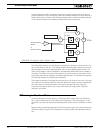
Another method uses the AX1500’s Emergency Stop input to shut down the controller if
any of the limit switches is tripped. Figure 54 shows the wiring diagram used in this case.
Each of the limit switches is a Normally Open switch. Two of these switches are typically
required for each motor. Additional switches may be added as needed for the second
motor and/or for a manual Emergency Stop. Since very low current flows through the
switches, these can be small, low cost switches.
The principal restriction of this technique is that it depends on the controller to be fully
functioning, and that once a switch is activated, the controller will remain inactive until the
switch is released. In most situations, this will require manual intervention. Another limita-
tion is that both channels will be disabled even if only one channel caused the fault.
Motor
SW1 SW2
Controller
FIGURE 53. Safety limit switches interrupting power to motors