AX1500 Motor Controller User’s Manual 89
Using Current Limiting as Protection
Important Warning
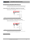
Limit switches must be used when operating the controller in Position Mode. This
will significantly reduce the risk of mechanical damage and/or injury in case of dam-
age to the position sensor or sensor wiring.
Using Current Limiting as Protection
It is a good idea to set the controller’s current limit to a low value in order to avoid high cur-
rent draws and consequential damage in case the motor does not stop where expected.
Use a value that is no more than 2 times the motor’s draw under normal load conditions.
Control Loop Description
The AX1500 performs the Position mode using a full featured Proportional, Integral and Dif-
ferential (PID) algorithm. This technique has a long history of usage in control systems and
works on performing adjustments to the Power Output based on the difference measured
between the desired position (set by the user) and the actual position (captured by the
position sensor).
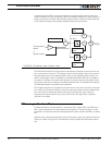
Figure 55 shows a representation of the PID algorithm. Every 16 milliseconds, the control-
ler measures the actual motor position and substracts it from the desired position to com-
pute the position error.
The resulting error value is then multiplied by a user selectable Proportional Gain. The
resulting value becomes one of the components used to command the motor. The effect
of this part of the algorithm is to apply power to the motor that is proportional with the dis-
tance between the current and desired positions: when far apart, high power is applied,
with the power being gradually reduced and stopped as the motor moves to the final posi-
tion. The Proportional feedback is the most important component of the PID in Position
mode.
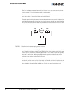
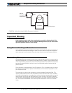
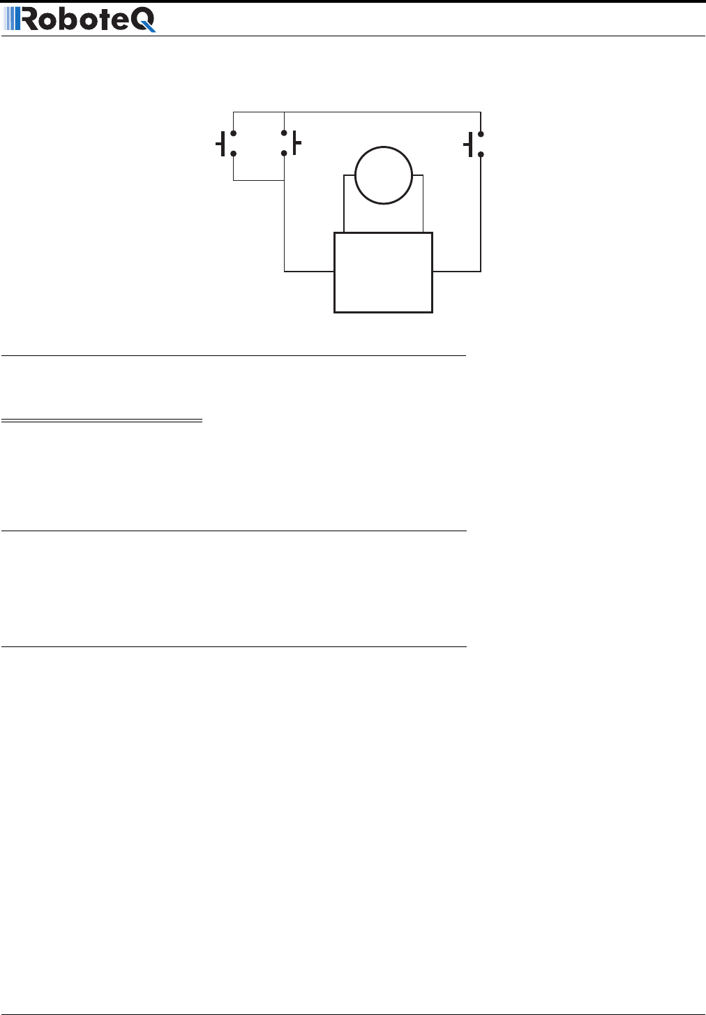
Motor
SW1
SW2
Manual
Emergency
Stop Switch
Emergency Stop InputGround
Controller
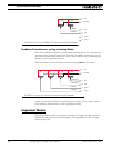
FIGURE 54. Safety limit using AX1500’s Emergency Stop input


