


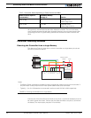
Connecting Power and Motors to the Controller
34 AX1500 Motor Controller User’s Manual Version 1.9b. June 1, 2007
It will be safe to wire in parallel the controller’s outputs only after you have verified that
both outputs react identically to channel 1 commands.
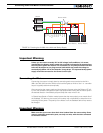
Power Fuses
For low Amperage applications (below 30A per motor), it is recommended that a fuse be
inserted in series with the main battery circuit as shown in the Figure 9 on page 30.
The fuse will be shared by the two output stages and therefore must be placed before the
Y connection to the two power wires. Fuse rating should be the sum of the expected cur-
rent on both channels. Note that automotive fuses are generally slow will be of limited
effectiveness in protecting the controller and may be omitted in high current application.
The fuse will mostly protect the wiring and battery against after the controller has failed.
Important Warning
Fuses are typically slow to blow and will thus allow temporary excess current to flow
through them for a time (the higher the excess current, the faster the fuse will blow).
This characteristic is desirable in most cases, as it will allow motors to draw surges
during acceleration and braking. However, it also means that the fuse may not be
able to protect the controller.
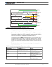
Wire Length Limits
The AX1500 regulates the output power by switching the power to the motors On and Off
at high frequencies. At such frequencies, the wires’ inductance produces undesirable
effects such as parasitic RF emissions, ringing and overvoltage peaks. The controller has
built-in capacitors and voltage limiters that will reduce these effects. However, should the
wire inductance be increased, for example by extending the wire length, these effects will
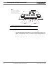
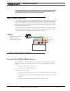
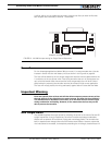
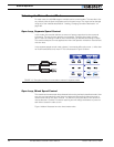
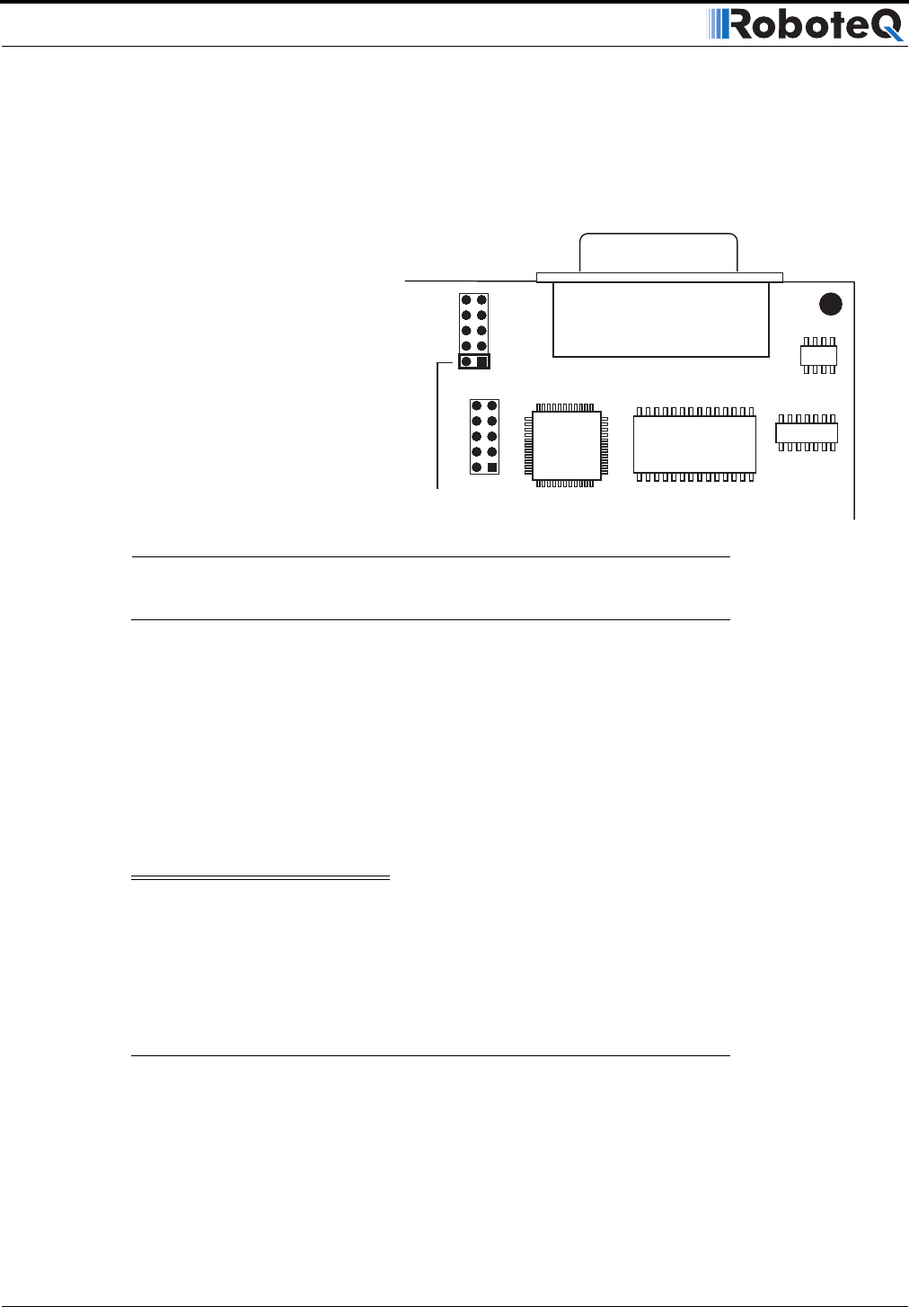
Xilinx
Jumper In for Single Channel
MCU
FIGURE 12. AX1500 Jumper setting for Single Channel Operation