


AX1500 Motor Controller User’s Manual 63
Connecting User Devices to Analog Inputs
Measured volts = ((controller reading + 128) * 0.255) -5
Note: The A/D converter’s reading is returned by the ?p command and is a signed 8-bit
hexadecimal value. You must add 128 to bring its range from -127/+127 to 0/255.
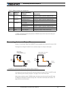
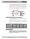
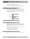
Connecting User Devices to Analog Inputs
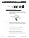
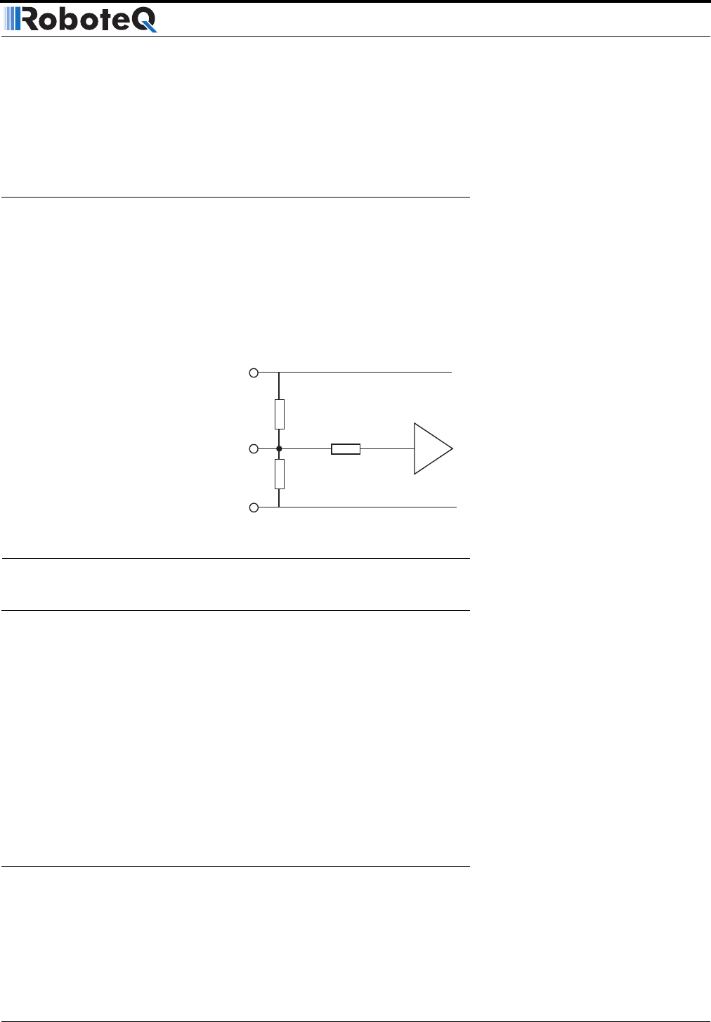
The two analog inputs can be used for any other purpose. The equivalent circuit for each
input is shown in Figure 33. The converter operates with an 8-bit resolution, reporting a
value of 0 at 0V and 255 at +5V. Care should be taken that the input voltage is always posi-
tive and does not exceed 5V. The converter’s intrinsic diodes will clip any negative voltage
or voltage above 5V, thus providing limited protection. The value of the analog inputs can
be read through the controller’s RS232 port.
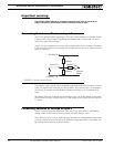
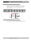
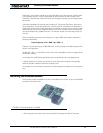
Internal Voltage Monitoring Sensors
The AX1500 incorporates voltage sensors that monitor the Main Battery voltage and the
Internal 12V supply. This information is used by the controller to protect it against overvolt-
age and undervoltage conditions (see “Overvoltage Protection” on page 36 and “Under-
voltage Protection” on page 36). These voltages can also be read from the RS232 serial
port using the ?e query.
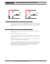
The returned value are numbers ranging from 0 to 255. To convert these numbers into a
Voltage figure, the following formulas must be used:
Measured Main Battery Volts = 55 * Read Value / 256
Measured Internal Volts = 28.5 * Read Value / 256
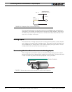
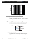
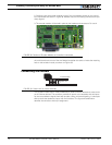
Internal Heatsink Temperature Sensors
The AX1500 includes temperature sensors near the transistor of each of the two output
stages.
47kOhm
10kOhm
47kOhm
+5V 14
Ground 5
A/D
Ana 1: 11
Ana 2: 10
Ana 3: 12
Ana 4: 8
FIGURE 33. AX1500 Analog Input equivalent circuit