


AX1500 Motor Controller User’s Manual 55
Connecting devices to Output C
**These connections should only be done in RS232 mode or R/C mode with radio pow-
ered from the controller.
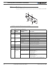
Connecting devices to Output C
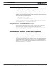
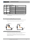
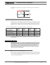
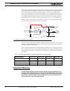
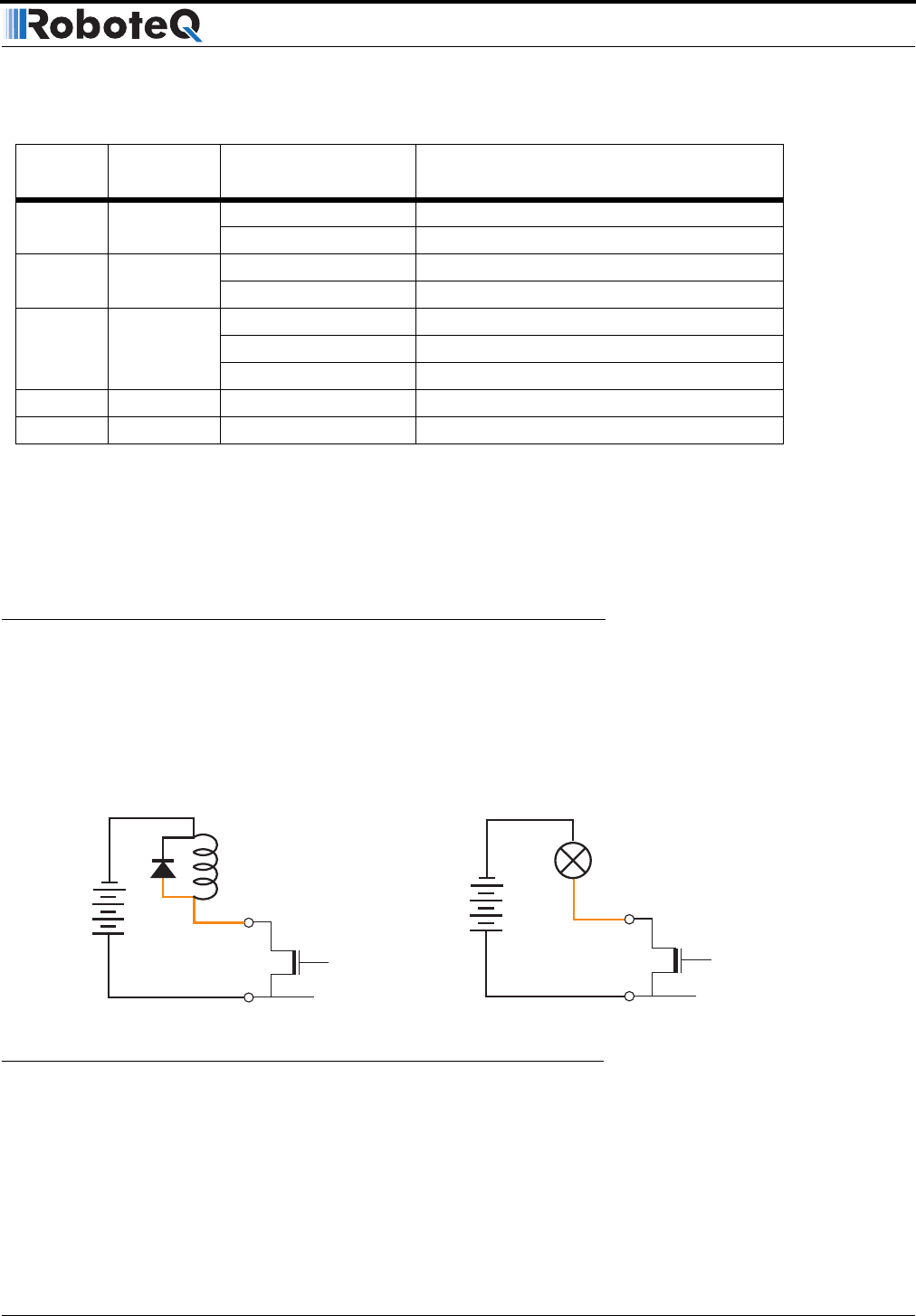
Output C is a buffered, Open Drain MOSFET output capable of driving over 2A at up to 24V.
The diagrams on Figure 23 show how to connect a light or a relay to this output:
This output can be turned On and Off using the Channel 3 Joystick when in the R/C mode.
See “Activating the Accessory Outputs” on page 110 for more information.
When the controller is used in RS232 mode, this output can be turned On and Off using
the !C (On) and !c (Off) command strings. See “Controller Commands and Queries” on
page 128 for more information.
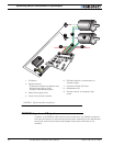
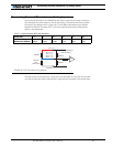
10 Analog in
RC/RS232: Ana in 2 Channel 2 speed or position feedback input
Analog: Command 2 Analog command for channel 2
11 Analog in RC/RS232: Ana in 1 Channel 1 speed or position feedback input
Analog: Command 1 Analog command for channel 1
12 Analog in RC: Unused
RS232: Ana in 3 Analog input 3
Ana: Ana in 3 Channel 1 speed or position feedback input
14 Power Out +5V +5V Power Output (100mA max.)
15 Input Input EStop/Inv Emergency Stop or Invert Switch input
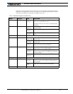
TABLE 8. DB15 connector pin assignment
Pin
Number
Input or
Output
Signal depending
on Mode Description
5 to
24V
DC
Output C 1,9
Internal
Transistor
Relay, Valve
Motor, Solenoid
or other Inductive Load
Ground 5
+
-
5 to
24V
DC
Output C 1,9
Internal
Transistor
Lights, LEDs, or any other
non-inductive load
Ground 5
+
-
FIGURE 23. Connecting inductive and resistive loads to Output C