


152 AX1500 Motor Controller User’s Manual Version 1.9b. June 1, 2007
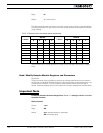
*9A
*9B - Least Significant Byte
These two 32-bit (4-bytes) registers are used to store the desired destination when the
controller is used in position mode. These registers should always be set using the mailbox
mechanism described above. See “Using the Encoder to Track Position” on page 77 for a
complete description of the position mode.
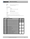
Distance 1 and 2
Address: *9C - Channel 1
*9D - Channel 2
These registers contain a signed 8-bit value (-127 to +127) that represents the distance
between the current counter position and the desired destination. This number is com-
puted using a formula described in section “Using the Encoder to Track Position” on
page 77.
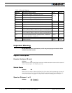
Speed 1 and 2
Address: *9E - Channel 1
*8F - Channel 2
These registers contain a signed 8-bit value (-127 to +127) that represents the motor speed
relative to a maximum speed, which in turn depends on the number of encoder counts and
time base settings as described in “Using the Encoder to Measure Speed” on page 76.
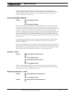
Time Base 1 and 2
Address: *A2 - Channel 1
*A3 - Channel 2
These registers contain the timing information for measuring the speed. See “Using the
Encoder Module to Measure Distance” on page 76 for a detailed description.
Encoder Threshold
Address: *A4
This register contains a value that is used to detect a logic level 1 vs. a 0 at any of the 4
encoder input lines. The voltage threshold is computed as follows:
Voltage Threshold = 5V * Register Value / 255
See “Voltage Levels, Thresholds and Limit Switches” on page 72 for a detailed description.
Distance Divider
Address: *A5
This registers contain the divider ratio that is applied to the difference between the current
position and destination. See “Using the Encoder Module to Measure Distance” on
page 76 for a detailed description.