


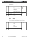

Serial (RS-232) Controls and Operation
132 AX1500 Motor Controller User’s Manual Version 1.9b. June 1, 2007
ages: the first is the Main Battery voltage present at the thick red and black wires. The sec-
ond is the internal 12V supply needed for the controller’s microcomputer and MOSFET
drivers. The values are unsigned Hexadecimal numbers ranging from 0 to 255. To convert
these numbers into a voltage figure, use the formulas described in “Internal Voltage Moni-
toring Sensors” on page 63.
Syntax: ?e or ?E
Reply: nn
mm
Where: nn = main battery voltage value
mm = internal 12V voltage value
Notes:
The hexadecimal format is intended to be deciphered by a microcontroller. When exercis-
ing the controller manually, refer to the Decimal to Hexadecimal conversion table on
page 157.
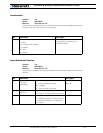
Query Digital Inputs
Description:
This query will cause the controller to return the state of the controller’s two accessory
inputs (inputs E and F) and the state of the Emergency Stop/Inverted input. See “Connect-
ing Sensors and Actuators to Input/Outputs” on page 51 for information on how to wire
and use these signals. The returned values are three sets of two digits with the values 00
(to indicate a 0 or Off state), or 01 (to indicate a 1 or On state).
Syntax: ?i or ?I
Reply: nn
mm
oo
Where: nn = Input E status
mm = Input F status
oo = Estop/Invert Switch Input status
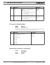
Examples:
?I Read Input status query
01 Controller replies, Input E is On
00 Input F is Off
01 Emergency stop switch is high (not triggered)
Note: the Input E value is not meaningful if the encoder module is present and should be
discarded.
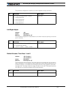
Reset Controller
Description:
This command allows the controller to be reset in the same manner as if the reset button
were pressed. This command should be used in exceptional conditions only or after chang-
ing the controller’s parameters in Flash memory so that they can take effect.
Syntax: %rrrrrr