


R/C Operation
106 AX1500 Motor Controller User’s Manual Version 1.9b. June 1, 2007
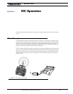
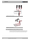
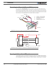
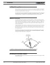
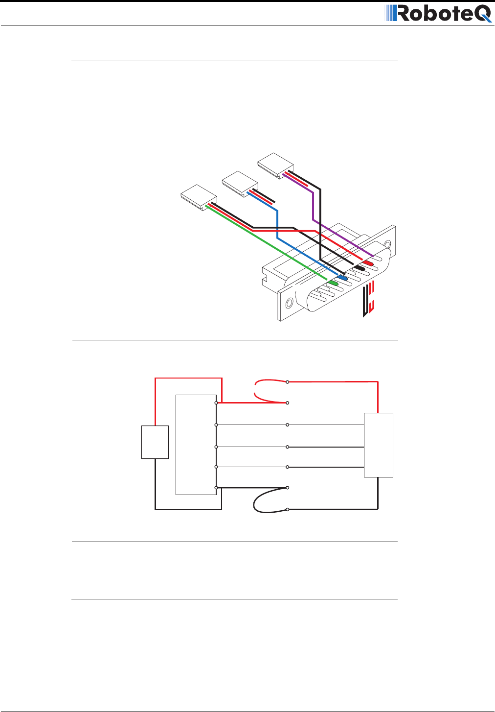
Connecting to a Separately Powered Radio
This wiring option must be used when the controller is used with a RC receiver that is
powered by its own separate battery. The red wire in the loop must be cut so that the 5V
out from the controller does not flow to the radio, and so that the battery that is connected
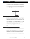
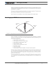
to the controller does not inject power into the controller. The figure below show the cable
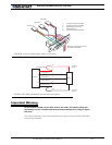
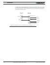
with the loop cut. Figure 69 shows the equivalent electrical diagram.
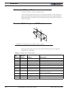
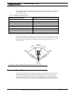
Operating the Controller in R/C mode
In this operating mode, the AX1500 will accept commands from a Radio Control receiver
used for R/C models remote controls. The speed or position information is communicated
to the AX1500 by the width of a pulse from the R/C receiver: a pulse width of 1.0 millisec-
8
9
15
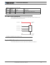
Pin 1
Channel 1
Channel 2
3: Channel 1 Command Pulses
4: Channel 2 Command Pulses
6: Radio battery (-) Ground
7: Radio battery (+)
8: Channel 3 Command Pulses
Channel 3:
Cut red loop
FIGURE 68. Wiring when receiver is powered by its own separate battery
Controller
Power
R/C Radio Power
Cut
Radio
Battery
R/C Radio
R/C Channel 1
R/C Channel 2
R/C Radio Ground
Controller
Ground
R/C Channel 3
14
3
7
8
6
5-13
4
MCU
FIGURE 69. Electrical diagram for connection to independently powered RC radio