


AX1500 Motor Controller User’s Manual 143
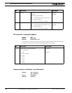
Reading & Changing Operating Parameters at Runtime
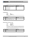
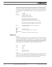
^86 - I2
^87 - D2
Access: Read/Write
Effective: Instantly
The Proportional, Integral and Derivative gain for each channel can be read and changed on-
the-fly. This function also provides a mean for setting different PID values for each channel.
Actual Gain value is the value contained in the register divided by 8. Changes take effect at
the controller’s next 16ms iteration loop. After reset, these bits get initialized according to
the configuration contained in Flash.
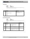
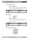
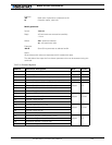
PWM Frequency Register
Address: ^88
Access: Read/Write
Effective: Instantly
The controller’s default 16kHz PWM Frequency can be changed to a higher value in fine
increments. This feature may be used to reduce the interference in case the controller’s
PWM frequency harmonics are too close to the radio receiver’s frequency. The value can
be changed at any time and takes effect immediately. The frequency is:
15,625 Hz * 255 / Register Value
The controller’s default frequency provides the best efficiency and should be changed only
if absolutely required and only if operating the controller in RS232 or Analog modes.
Changes to the PWM frequency will affect the RS232 watchdog timer and PID may need
re-tuning.
The controller automatically reverts to the default 16kHz PWM frequency after reset.
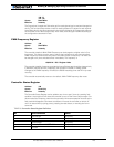
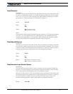
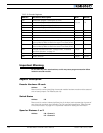
Controller Status Register
Address: ^89
Access: Read Only
Effective: Instantly
The Controller Status Register can be polled at any time to see if there is a pending fault
condition. Any one bit set will cause the controller to turn off the Power Output stage. Con-
ditions marked as Temporary mean that the controller will resume operation as soon as the
fault condition disappears. Permanent conditions will cause the controller to remain off
until it is reset either by cycling power, pressing the reset button, or sending the %rrrrrr
command.
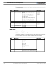
TABLE 25. Controller Status Register Definition
Bit Fault Condition Effect
0 Overvoltage Temporary
1 Overtemperature Temporary
2 Undervoltage Temporary
3 Manually Forced MOSFETs Off Temporary
4Unused