


Installing, Connecting and Using the Encoder Mod-
68 AX1500 Motor Controller User’s Manual Version 1.9b. June 1, 2007
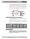
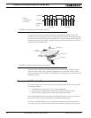
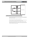
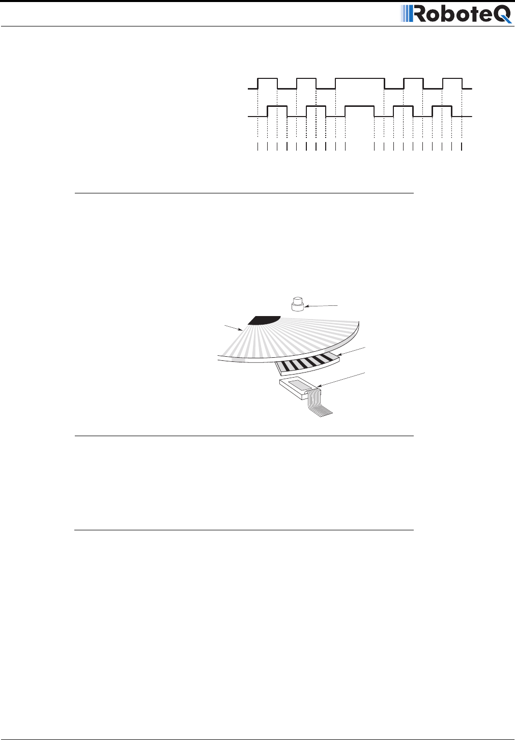
The figure below shows the typical construction of a quadrature encoder. As the disk
rotates in front of the stationary mask, it shutters light from the LED. The light that passes
through the mask is received by the photo detectors. Two photo detectors are placed side
by side at so that the light making it through the mask hits one detector after the other to
produces the 90o phased pulses.
Unlike absolute encoders, incremental encoders have no retention of absolute position
upon power loss. When used in positioning applications, the controller must move the
motor until a limit switch is reached. This position is then used as the zero reference for all
subsequent moves.
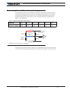
Recommended Encoder Types
The module may be used with most incremental encoder module as long as they include
the following features:
• Two quadrature outputs (Ch A, Ch B), single ended signal
• 2.5V minimum swing between 0 Level and 1 Level on quadrature output
• 5VDC operation. 100mA or less current consumption per encoder
More sophisticated incremental encoders with differential outputs, index, and other fea-
tures may be used, however these additional capabilities will be ignored.
The choice of encoder resolution is very wide and is constrained by the module’s maxi-
mum pulse count at the high end and measurement resolution for speed at the low end.
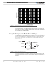
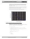
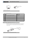
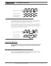
A Channel
Count Up
Count Down
B Channel
Quadrature
Signal
FIGURE 35. Quadrature encoder output waveform
1 Pulse
= 4 Transitions
= 4 Counts
LED light source
Stationary mask
Photodetector
Rotating
encoder disk
FIGURE 36. Typical quadrature encoder construction