


AX1500 Motor Controller User’s Manual 49
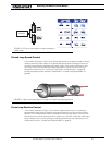
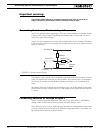
Activating Brake Release or Separate Motor Excitation
Activating Brake Release or Separate Motor Excitation
The controller may be configured so that the Output C will turn On whenever one of the
two motors is running. This feature is typically used to activate the mechanical brake
release sometimes found on motors for personal mobility systems. Likewise, this output
can be used to turn on or off the winding that creates the armature’s magnetic field in a
separate excitation motor. This function is disabled by default and may be configured using
the Roborun PC utility. See “Loading, Changing Controller Parameters” on page 164. See
“Connecting devices to Output C” on page 55 for details on how to connect to the output.
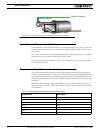
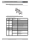
Emergency Stop using External Switch
An external switch can be added to the AX1500 to allow the operator to stop the control-
ler’s output in case of emergency. This controller input can be configured as the “Inverted”
detection instead of Emergency Stop. The factory default for this input is “No Action”.
The switch connection is described in “Connecting Switches or Devices to EStop/Invert
Input” on page 57. The switch must be such that it is in the open state in the normal situa-
tion and closed to signal an emergency stop command.
After and Emergency Stop condition, the controller must be reset or powered Off
and On to resume normal operation.
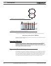
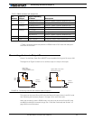
Inverted Operation
For robots that can run upside-down, the controller can be configured to reverse the motor
commands using a gravity activated switch when the robot is flipped. This feature is
enabled only in the mixed mode and when the switch is enabled with the proper configura-
tion of the “Input switch function” parameter. See “Programmable Parameters List” on
page 175.
The switch connection is described in “Connecting Switches or Devices to EStop/Invert
Input” on page 57. The switch must be such that it is in the open state when the robot is in
the normal position and closed when inverted. When the status of the switch has changed,
the controller will wait until the new status has remained stable for 0.5s before acknowl-
edging it and inverting the commands. This delay is to prevent switch activation triggered
by hits and bounces which may cause the controller to erroneously invert the commands.
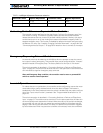
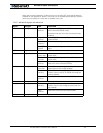
5 -1.5% 12 4.5%
6 -0.75% 14 5.25%
TABLE 6. Left/Right Adjustment Parameter selection
Parameter Value Speed Adjustment Parameter Value Speed Adjustment