


AX1500 Motor Controller User’s Manual 17
Connecting to the Batteries and Motors
Connecting to the Batteries and Motors
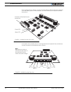
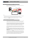
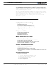
Connection to the batteries and motors is shown in the figure below and is done by con-
necting wires to the controller’s terminal strip.
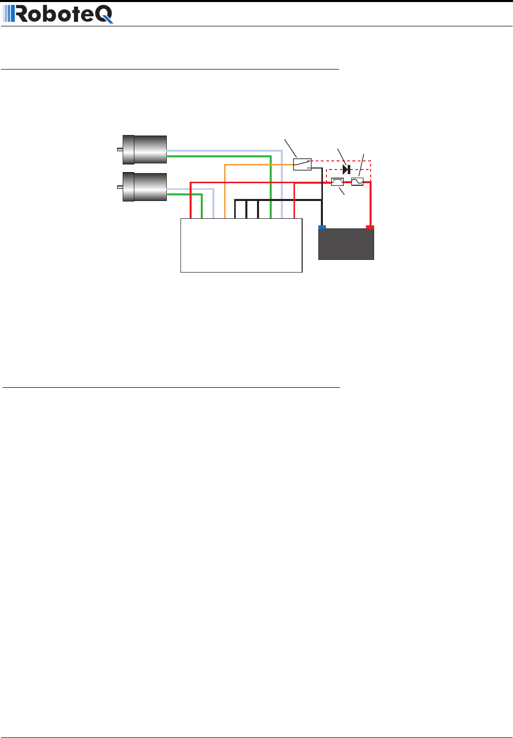
1- Connect each motor to one of the two M+ and M- terminal pairs. Make sure to respect
the polarity, otherwise the motor(s) may spin in the opposite direction than expected
2- Connect two of the three Ground terminals to the minus (-) terminal of the battery that
will be used to power the motors. Connect the two VMot terminals to the plus (+) terminal
of the battery. The motor battery may be of 12 to 40 Volts. There is no need to insert a sep-
arate switch on Power cables, although one is suggested for Emergency disconnect. See
“Controller Power” on page 28 for a detailed discussion and more wiring options.
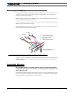
Avoid extending the length of wires from the battery to the controller as the added induc-
tance may cause damage to the controller when operating at high currents. Try extending
the motor wires instead since the added inductance on the motor side of the controller is
not harmful.
The two VMot terminals are connected to each other inside the controller. The same
is true for the Ground Terminals. You should wire each pair together as shown in the
diagram above.
3- The Power control terminal MUST be connected to Ground to turn the Controller Off.
For turning the controller On, even though the Power Control may be left floating, when-
ever possible pull it to an unfused12V or higher voltage to keep the controller logic solidly
On. You may use a separate battery to keep the controller alive as the main Motor battery
discharges. Refer to the chapter “Connecting Power and Motors to the Controller” on
page 27 for more information about batteries and other connection options.
12V to 24V
Motor Battery
Power switch
On
Off
Optional
Emergency
Disconnect
Optional
Diode
-
-
+
+
Motor1
Motor2
Controller
Fuse
VMot
VMot
M1-
M1+
PwrCtrl
GND
GND
GND
M2+
M2-
Notes:
- The Battery Power connection are doubled in order to provide the maximum current to the controller. If
only one motor is used, only one set of motor power cables needs to be connected.
- Typically, 1, 2 or 3 x 12V batteries are connected in series to reach 12, 24 or 36V respectively.
- The Power Control wire MUST be used to turn On and Off the controller.
FIGURE 3. AX1500 Electrical Power Wiring Diagram