


AX1500 Motor Controller User’s Manual 73
Wiring Optional Limit Switches
In Figure 42, the encoder and switches are wired to the encoder module using a set of
resistors designed to create a multi-level signal combining both pieces of information.
Details on the necessary wiring is provided in the next section.
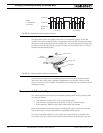
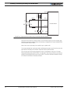
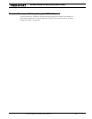
Since the encoder output signal is “shifted-up” by a few volts, it always stays above the
Limit Switch comparator’s threshold, and no Switch Detection condition is generated.
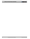
However, since the limit switches connect to ground when On, the level will dip below the
0.5V and generate a Switch Detection condition.
Important Warning
When a limit switch is activated, the encoder signal that is shared with the switch is
no longer visible by the encoder module, and pulse counting and speed measure-
ment stops.
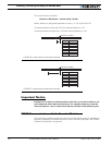
Wiring Optional Limit Switches
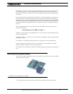
If limit switches are needed by the application, additional circuitry is required in order to
create a multi-level signal that shares the encoder and the switch information. The figure
below shows the electrical diagram of the required wiring.
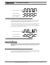
2.5V
0.5V
Signal on Channel A or B
Quadrature Signal
Switch Detect Signal
(Not meaningful)
FIGURE 42. Signals seen by encoder using direct connection and no limit switches
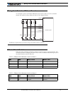
2.5V
0.5V
Signal on Channel A or B
Quadrature Signal
Switch Detect Signal
FIGURE 43. Signals seen by encoder using multi-levels and limit switches