


Closed Loop Speed Mode
96 AX1500 Motor Controller User’s Manual Version 1.9b. June 1, 2007
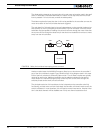
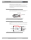
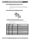
Adjust Offset and Max Speed
For proper operation, the controller must see a 0 analog speed value (2.5V voltage on the
analog input).
To adjust the 0 value when the motors are stopped, use the Roborun utility to view the
analog input value while the tachometer is not turning. Move the 0 offset potentiometer
until a stable 0 is read. This should be right around the potentiometer’s middle position.
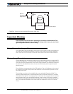
The tachometer must also be calibrated so that it reports a +127 or -127 analog speed
value (5V or 0V on the analog input, respectively) when the motors are running at the max-
imum desired speed in either direction. Since most tachometers will generate more than
+/- 2.5V, a 10kOhm potentiometer must be used to scale its output.
To set the potentiometer, use the Roborun utility to run the motors at the desired maxi-
mum speed while in Open Loop mode (no speed feedback). While the tachometer is spin-
ning, adjust the potentiometer until the analog speed value read is reaching 126.
Note: The maximum desired speed should be lower than the maximum speed that the
motors can spin at maximum power and no load. This will ensure that the controller will be
able to eventually reach the desired speed under most load conditions.
Important Warning:
It is critically important that the tachometer and its wiring be extremely robust. If the
tachometer reports an erroneous voltage or no voltage at all, the controller will con-
sider that the motor has not reached the desired speed value and will gradually
increase the applied power to the motor to 100% with no way of stopping it until
power is cut off or the Emergency Stop is activated.
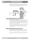
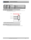
Control Loop Description
The AX1500 performs the Closed Loop Speed mode using a full featured Proportional, Inte-
gral and Differential (PID) algorithm. This technique has a long history of usage in control
systems and works on performing adjustments to the Power Output based on the differ-
ence measured between the desired speed (set by the user) and the actual position (cap-
tured by the tachometer).
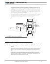
Figure 58 shows a representation of the PID algorithm. Every 16 milliseconds, the control-
ler measures the actual motor speed and subtracts it from the desired position to compute
the speed error.
The resulting error value is then multiplied by a user selectable Proportional Gain. The
resulting value becomes one of the components used to command the motor. The effect
of this part of the algorithm is to apply power to the motor that is proportional with the dif-
ference between the current and desired speed: when far apart, high power is applied,
with the power being gradually reduced as the motor moves to the desired speed.
A higher Proportional Gain will cause the algorithm to apply a higher level of power for a
given measured error thus making the motor react more quickly to changes in commands
and/or motor load.