


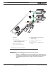
Connecting Sensors and Actuators to Input/Outputs
60 AX1500 Motor Controller User’s Manual Version 1.9b. June 1, 2007
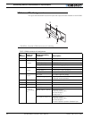
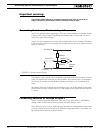
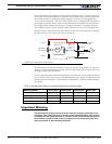
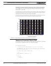
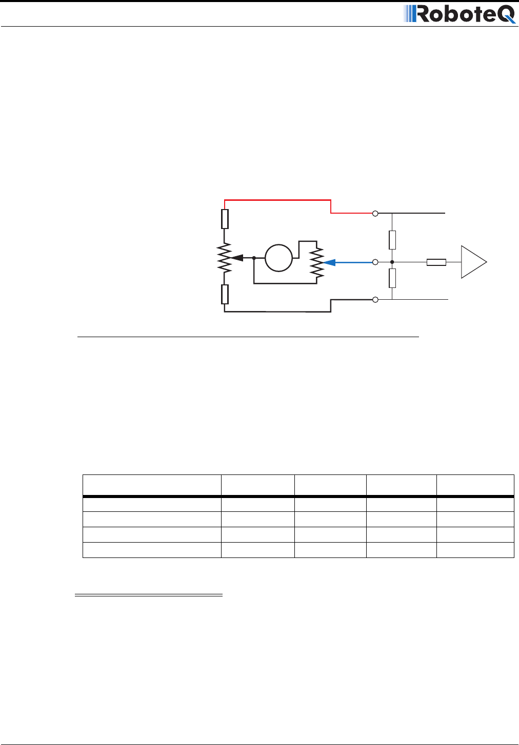
Since the controller only accepts a 0 to 5V positive voltage as its input, the circuit shown in
Figure 29 must be used between the controller and the tachometer: a 10kOhm potentiom-
eter is used to scale the tachometer output voltage to -2.5V (max reverse speed) and
+2.5V (max forward speed). The two 1kOhm resistors form a voltage divider that sets the
idle voltage at mid-point (2.5V), which is interpreted as the zero position by the controller.
The voltage divider resistors should be of 1% tolerance or better. To precisely adjust the
2.5V midpoint value it is recommended to add a 100 ohm trimmer on the voltage divider.
With this circuitry, the controller will see 2.5V at its input when the tachometer is stopped,
0V when running in full reverse, and +5V in full forward.
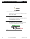
The tachometers can generate voltages in excess of 2.5 volts at full speed. It is important,
therefore, to set the potentiometer to the minimum value (cursor all the way down per this
drawing) during the first installation.
Since in closed loop control the measured speed is the basis for the controller’s power out-
put (i.e. deliver more power if slower than desired speed, less if higher), an adjustment and
calibration phase is necessary. This procedure is described in “Closed Loop Speed Mode”
on page 93.
Important Warning
The tachometer’s polarity must be such that a positive voltage is generated to the
controller’s input when the motor is rotating in the forward direction. If the polarity
is inverted, this will cause the motor to run away to the maximum speed as soon as
the controller is powered with no way of stopping it other than pressing the emer-
gency stop button or disconnecting the power.
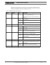
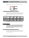
TABLE 10. Analog Speed Sensor connection depending on operating mode
Operating Mode Ana 1 (p11) Ana2 (p10) Ana 3 (p12) Ana 4 (p8)
RC or RS232 - Dual Channel Speed 1 Speed 2 Unused Unused
Analog - Dual Channel Command 1 Command 2 Speed 1 Speed 2
RC or RS232 - Single Channel Speed Unused Unused Unused
RC or RS232 - Dual Channel Command Unused Speed Unused
47kOhm
10kOhm
47kOhm
1kOhm
Max Speed Adjust
10kOhm pot
Zero Adjust
100 Ohm pot
1kOhm
Internal Resistors
and Converter
+5V 14
Ground 5
A/D
Ta c h
Ana 1: 11
Ana 2: 10
Ana 3: 12
Ana 4: 8
FIGURE 29. Tachometer wiring diagram