


AX1500 Motor Controller User’s Manual 53
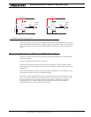
AX1500’s Inputs and Outputs
When the controller operates in modes that do not use these I/O, these signals become
available for user application. Below is a summary of the available signals and the modes in
which they are used by the controller or available to the user.
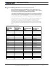
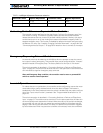
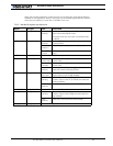
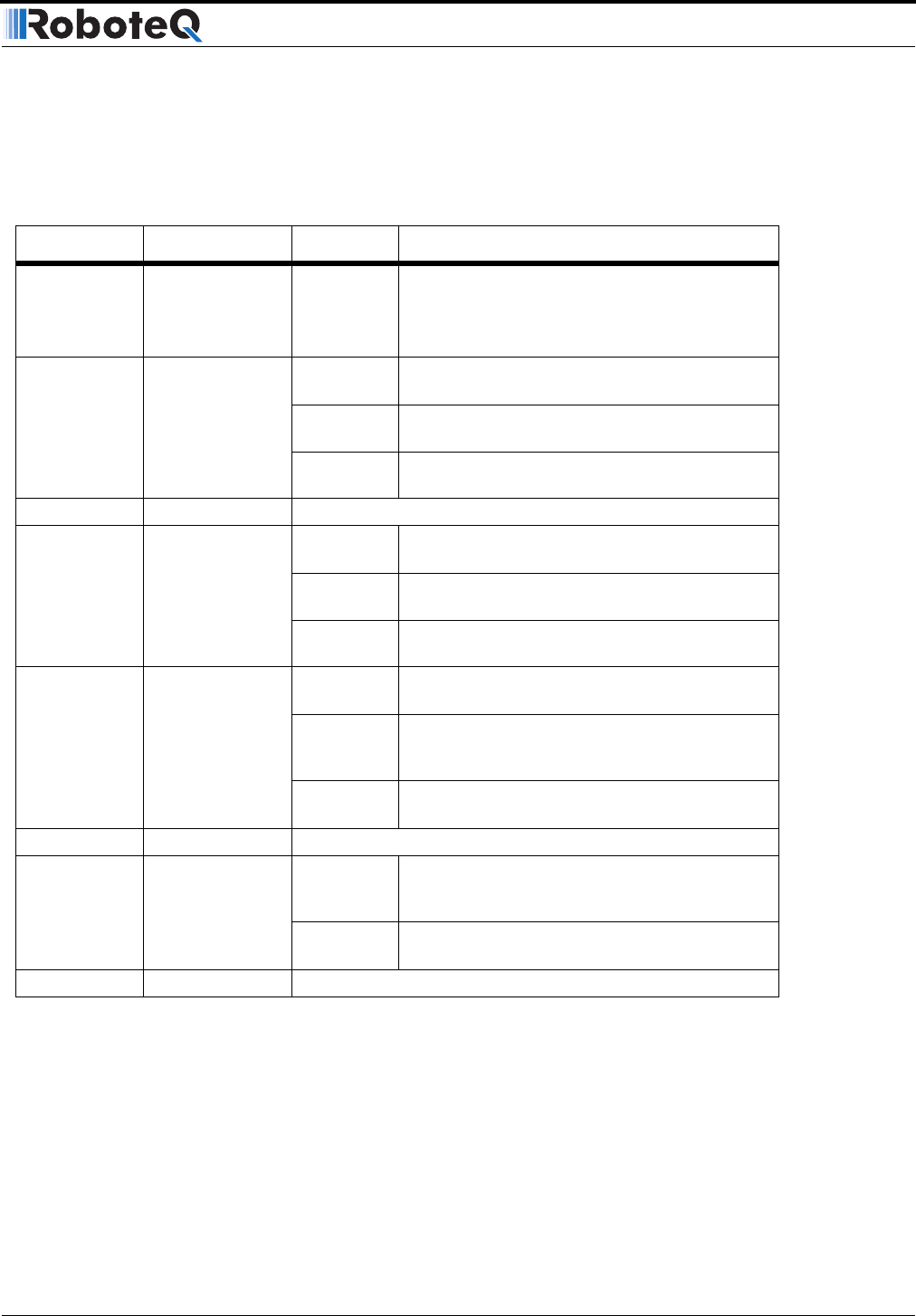
TABLE 7. AX1500 IO signals and definitions
Signal I/O type Use Activated
Out C 2A Digital Output User
defined
Activated using R/C channel 3 (R/C mode), or
serial command (RS232 mode)
Activated when any one motor is powered (when
enabled)
Inp F Digital Input User
defined
Active in RS232 mode only. Read with serial com-
mand (RS232)
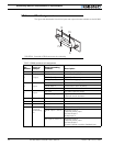
Activate
Output C
When Input is configured to drive Output C
Turn FETs
On/Off
When Input is configured as “dead man switch”
input
Inp E Digital Input Same as Input F - (Not available when encoder module present)
EStop/Invert Digital Input Emer-
gency stop
When Input is configured as Emergency Stop
switch input.
Invert
Controls
When Input is configured as Invert Controls
switch input.
User
defined
When input is configured as general purpose.
Read with serial command (RS232).
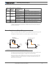
Analog In 1 Analog Input Tachome-
ters input
When Channel 1 is configured in Closed Loop
Speed Control with Analog feedback
Position
sensing
When Channel 1 is configured in Closed Loop
Position Control with RC or RS232 command and
Analog feedback
User
defined
Read value with serial command (RS232).
Analog In 2 Analog Input 2 Same as Analog 1 but for Channel 2
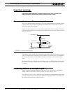
Analog In 3 Analog Input 3 Position
sensing
When Channel 1 is configured in Closed Loop
Position Control with Analog command and Ana-
log feedback
User
defined
Read value with serial command (RS232).
Analog In 4 Analog Input 4 Same as Analog 3 but for Channel 4