


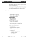
AX1500 Motor Controller User’s Manual 29
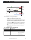
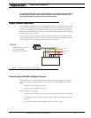
Controller Power
When powered only via the Power Control input, the controller will turn On but motors will
not be able to turn until power is also present on the VMot terminals.
The Power Control input also serves as the Enable signal for the DC/DC converter. When
floating or pulled to above 1V, the DC/DC converter is active and supplies the AX1500’s
microcomputer and drivers, thus turning it On. When the Power Control input is pulled to
Ground, the DC/DC converter is stopped and the controller is turned Off.
The Power control terminal MUST be connected to Ground to turn the Controller Off. For
turning the controller On, even though the Power Control may be left floating, whenever
possible pull it to an unfused12V or higher voltage to keep the controller logic solidly On.
You may use a separate battery to keep the controller alive as the main Motor battery dis-
charges.
The table below shows the state of the controller depending on the voltage applied to
Power Control and Vmot.
TABLE 2. Controller Status depending on Power Control and VMot
Power Control input is
connected to
And Main Battery
Voltage is Action
Ground Any Voltage from 0V to 40V Controller is Off
Floating 0V Controller is Off. Not Recom-
mended Off Configuration.
Floating Between 8V and 10.5V Controller Logic is On
Power Stage is Disabled (under-
voltage condition)
Floating Between 10.5 and 40V Controller is On.
Power Stage is Active
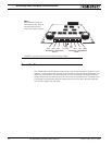
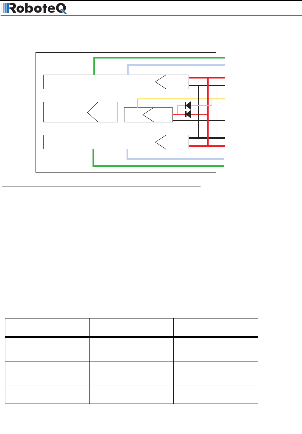
Channel 1 MOSFET Power Stage
Channel 2 MOSFET Power Stage
5Vmin
40V max
Microcomputer &
MOSFET Drivers
9.5V min
13V max
DC/DC
ENABLE
10.5V min
40V max
5Vmin
40V max
Power
Control
&Backup
VBatt Vmot
Mot1(-)
Mot2(-)
Mot1(+)
Mot2(+)
VBatt Vmot
GND
GND
GND
FIGURE 8. Representation of the AX1500’s Internal Power Circuits