


150 AX1500 Motor Controller User’s Manual Version 1.9b. June 1, 2007
Important Warning
Do not alter any other area locations, as this may cause program execution failure
inside the encoder module.
Register Description
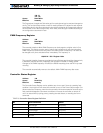
Encoder Hardware ID code
Address: *84
Returns a 4-bit number identifying the encoder module hardware version and the status of
two on-board jumpers. For Roboteq use only.
Switch Status
Address: *85
Returns a 4 bit number (4 least significant bits of the byte), each representing the state of
one of the limit switches when installed. The ?W command described at “Read Encoder
Limit Switch Status” on page 147 is a preferred method for reading this information.
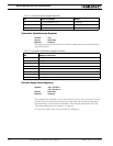
Speed or Distance 1 or 2
Address: *86 - Channel 1
*87 - Channel 2
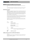
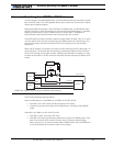
*98 Destination Register 1 MSB (bits 31 to 24)
4 bytes Full*99 Destination Register 1 (bits 23 to 16)
*9A Destination Register 1 (bits 15 to 8)
*9B Destination Register 1 LSB (bits 7 to 0)
*9C Distance 1 (when Position Mode enabled) 1 byte Full
*8D Distance 2 (when Position Mode enabled) 1 byte Full
*86 Speed 1 1 byte Full
*87 Speed 2 1 byte Full
*A2 Time Base for speed computation of Encoder 1. Multiply
this number by 256us to obtain the actual Time Base period.
1 byte Full
*A3 Time Base for speed computation of Encoder 2. Multiply
this number by 256us to obtain the actual Time Base period.
1 byte Full
*A4 Encoder threshold level (see “Voltage Levels, Thresholds
and Limit Switches” on page 72
1 byte Full
*A5 Distance divider 1 byte Full
*A6 Mode Selection 1 byte Limited
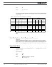
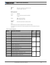
TABLE 28. Encoder Registers
Address Parameter Description Size Access