


AX1500 Quick Start
18 AX1500 Motor Controller User’s Manual Version 1.9b. June 1, 2007
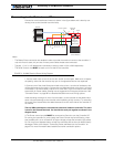
Important Warning
Do not rely on cutting power to the controller for it to turn off if the Power Control is
left floating. If motors are spinning because the robot is pushed are pushed or
because of inertia, they will act as generators and will turn the controller, possibly in
an unsafe state. ALWAYS ground the Power Control wire to turn the controller Off
and keep it Off.
Important Warning
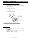
The controller includes large capacitors. When connecting the Motor Power Cables,
a spark will be generated at the connection point. This is a normal occurrence and
should be expected.
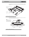
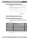
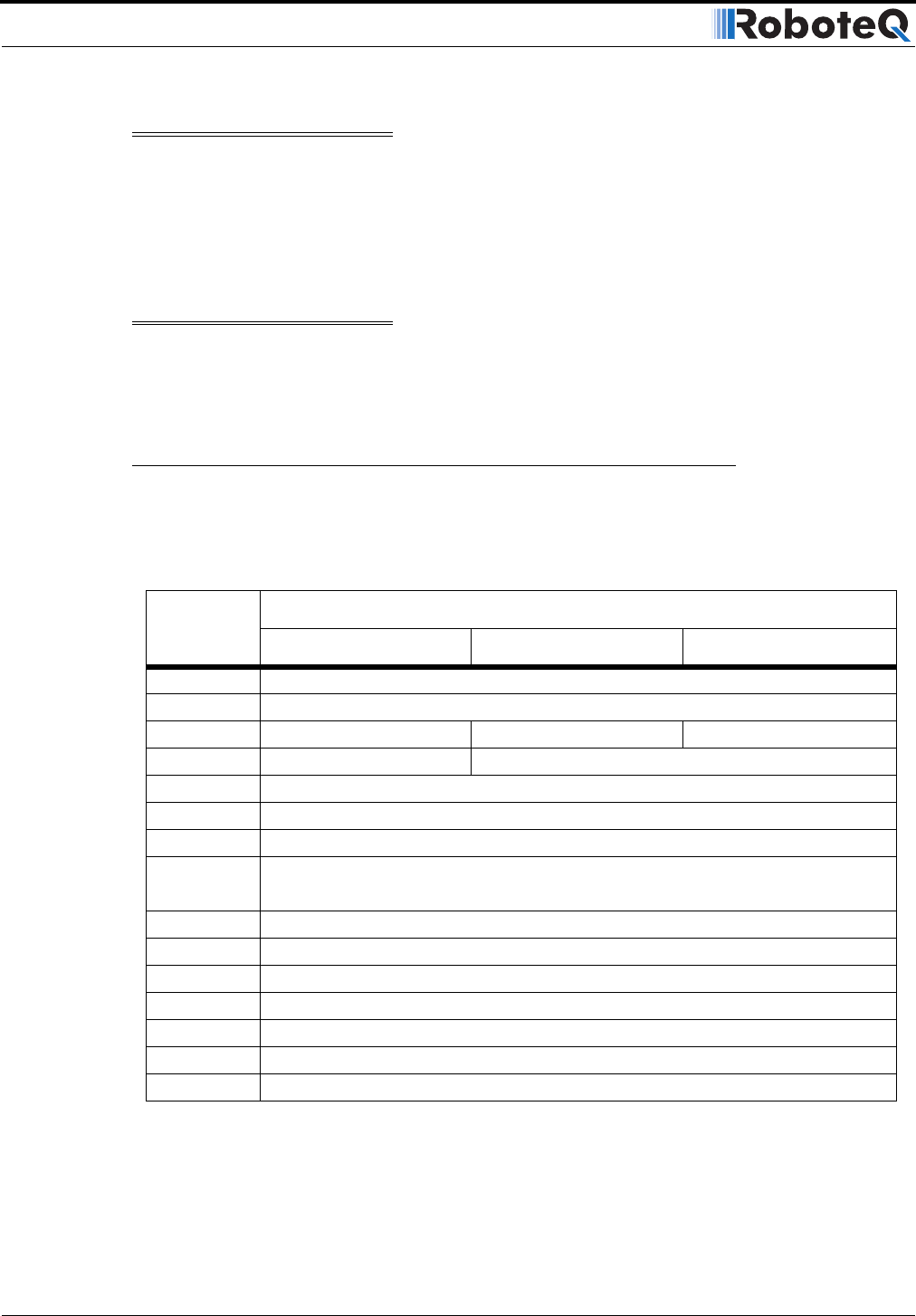
Connecting to the 15-pin Connector
The controller’s I/O are located on it’s standard 15-pin D-Sub Connector. The functions of
some pins varies depending on controller model and operating mode. Pin assignment is
found in the table below.
Pin
Signal
RC Mode RS232 Mode Analog Mode
1 2A Digital Output C (same as pin 9)
2TxData
3 RC Ch1 RxData Unused
4 RC Ch 2 Digital Input F
5 Ground Out
6 Unused
7 Unused
8 Digital Input E (Not available when Encoder module is present)
and Analog Input 4
9 2A Digital Output C (same as pin 1)
10 Analog Input 2
11 Analog Input 1
12 Analog Input 3
13 Ground Out
14 +5V Out (100mA max.)
15 Emergency Stop or Invert Switch input