


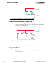


Closed Loop Position Mode
86 AX1500 Motor Controller User’s Manual Version 1.9b. June 1, 2007
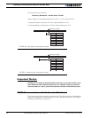
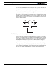
This wiring is also the one to use when the controller is in Analog mode but switched to
RS232 after reset using the method discussed in “Entering RS232 from R/C or Analog
mode” on page 126
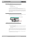
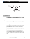
Using Optical Encoders in Position Mode
The AX2550 and AX1500 may be equipped with an optional Optical Encoder Module. Opti-
cal Encoders require special handling. See Figure 7, “Installing, Connecting and Using the
Encoder Module,” on page 67 for a detailed discussion.
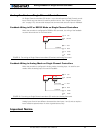
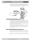
Sensor and Motor Polarity
The sensor polarity (i.e. which rotation end produces 0 or 5V) is related to the motor’s
polarity (i.e. which direction the motor turns when power is applied to it).
In the Position mode, the controller compares the actual position, as measured by the sen-
sor, to the desired position. If the motor is not at that position, the controller will apply
power to the motor so that it turns towards that destination until reached.
Important Warning:
If there is a polarity mismatch, the motor will turn in the wrong direction and the
position will never be reached. The motor will turn continuously with no way of
stopping it other than cutting the power or hitting the Emergency Stop button.
Determining the right polarity is best done experimentally using the Roborun utility (see
“Using the Roborun Configuration Utility” on page 161) and following these steps:
1. Disconnect the controller’s Motor Power (Vmot terminals).
2. Configure the controller in Position Mode using the PC utility.
3. Loosen the sensor’s axle from the motor assembly.
4. Launch the Roborun utility and click on the Run tab. Click the “Start” button to
begin communication with the controller. The sensor values will be displayed in the
Ana1 and Ana2 boxes.
5. Move the sensor manually to the middle position until a value of “0” is measured
using Roborun utility
6. Verify that the motor sliders are in the “0” (Stop) position. Since the desired posi-
tion is 0 and the measured position is 0, the controller will not attempt to move the
motors. The Power graph on the PC must be 0.
7. Apply power to the Motor Power input (Vmot terminals). The motor will be stopped.
8. With a hand ready to disconnect the Motor Power cable or ready to press the “Pro-
gram” and “Set” buttons at the same time (Emergency Stop), SLOWLY move the
sensor off the center position and observe the motor’s direction of rotation.
9. If the motor turns in the direction in which the sensor was moved, the polarity is
correct. The sensor axle may be tighten to the motor assembly.