


AX1500 Quick Start
16 AX1500 Motor Controller User’s Manual Version 1.9b. June 1, 2007
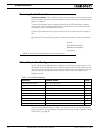
The front side (shown in Figure 1) contains the Power/Status LED and the 15-pin connector
to the R/C radio, joystick or microcomputer, as well as connections to optional switches
and sensors.
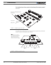
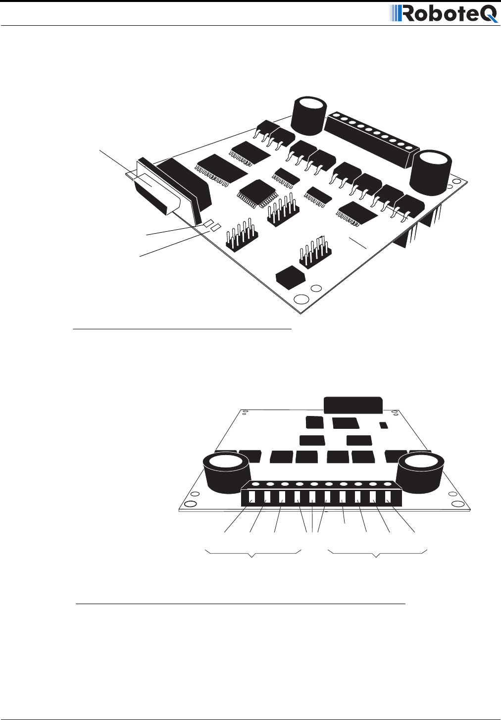
At the back of the controller (shown in the figure below) are located all the terminals that
must be connected to the batteries and the motors.
Status LED
FIGURE 1. AX1500 Controller Front View
Power LED
Connector to Receiver/Controls
and sensors
VMot
Motor 2 Motor 1
M2+ M1+ M1- VMotM2- 3 x Gnd
Pwr
Ctrl
FIGURE 2. AX1500 Controller Rear View
Note:
Both VMot terminals are
connected to each other in
the board and must be
wired to the same voltage.