


AX1500 Motor Controller User’s Manual 19
Connecting the R/C Radio
Connecting the R/C Radio
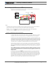
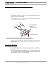
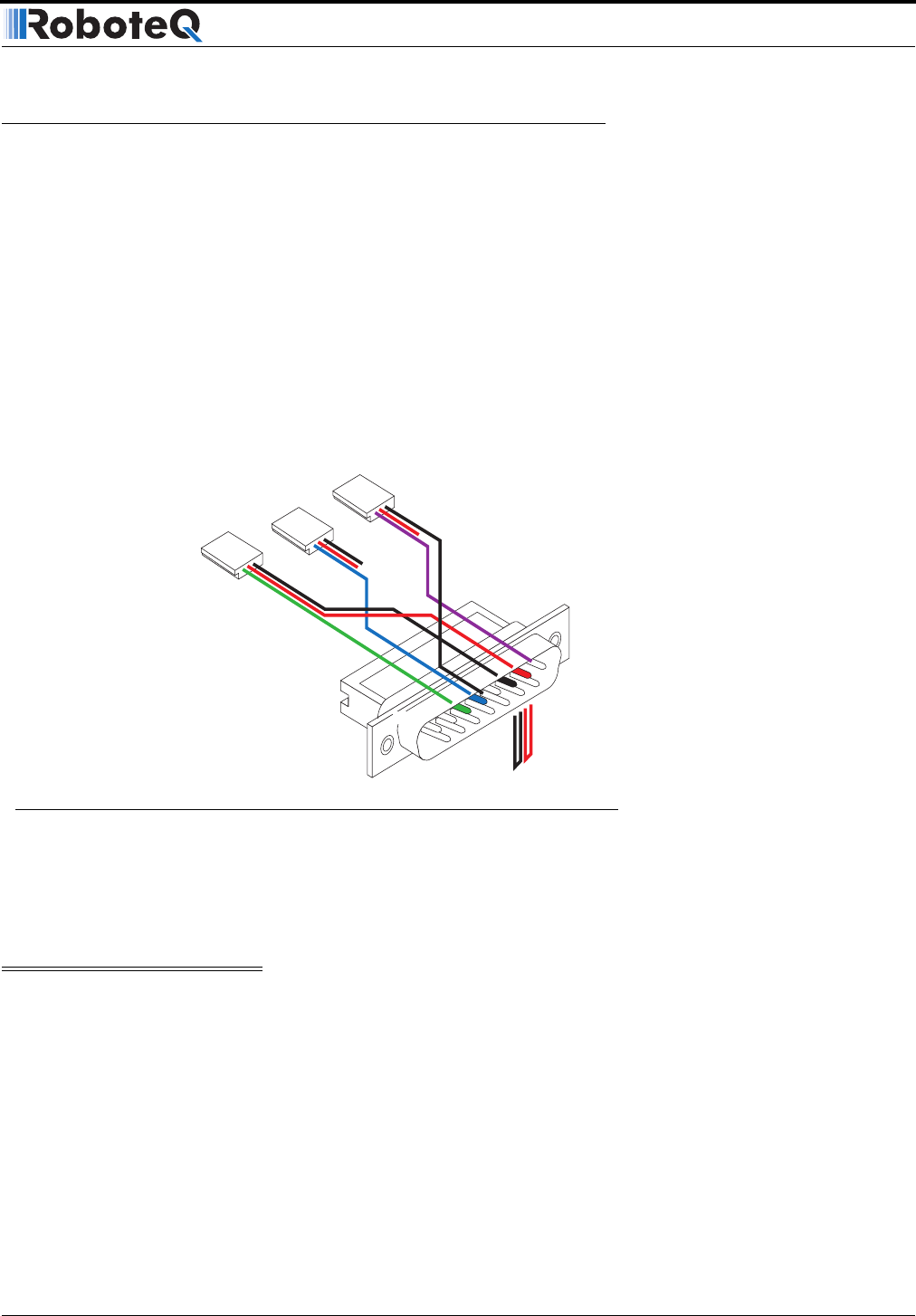
Connect the R/C adapter cables to the controller on one side and to two or three channels
on the R/C receiver on the other side. If present, the third channel is for activating the
accessory outputs and is optional.
When operating the controller in “Separate” mode, the wire labelled Ch1 controls Motor1,
and the wire labelled Ch2 controls Motor2.
When operating the controller in “Mixed” mode, Ch1 is used to set the robot’s speed and
direction, while Ch2 is used for steering.
See “R/C Operation” on page 101 of the User’s Manual for a more complete discussion on
R/C commands, calibration and other options.
This wiring - with the wire loop uncut - assumes that the R/C radio will be powered by the
AX1500 controller. Other wiring options are described in “R/C Operation” on page 101 of
the User’s Manual.
Important Warning
Do not connect a battery to the radio when the wire loop is uncut. The RC battery
voltage will flow directly into the controller and cause permanent damage if its volt-
age is higher than 5.5V.
Connecting the optional channel 3 will enable you to turn on and off the accessory output.
See “Connecting Sensors and Actuators to Input/Outputs” on page 51 and “Activating the
Accessory Outputs” on page 110 of the User’s Manual.
8
9
15
Pin 1
Channel 1
Wire loop bringing power from
controller to RC radio
Channel 2
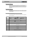
3: Channel 1 Command Pulses
4: Channel 2 Command Pulses
6: Radio battery (-) Ground
7: Radio battery (+)
8: Channel 3 Command Pulses
Channel 3
FIGURE 4. R/C connector wiring for 3 channels and battery elimination (BEC)