


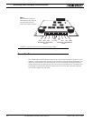
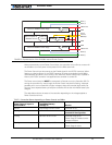
Connecting Power and Motors to the Controller
32 AX1500 Motor Controller User’s Manual Version 1.9b. June 1, 2007
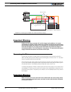
Important Warning
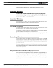
Unless you can ensure a steady 12V to 40V voltage in all conditions, it is recom-
mended that the battery used to power the controller’s electronics be separate from
the one used to power the motors. This is because it is very likely that the motor bat-
teries will be subject to very large current loads which may cause the voltage to
eventually dip below 12V as the batteries’ charge drops. The separate backup power
supply should be connected to the Power Control input.
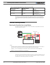
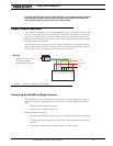
Connecting the Motors
Connecting the motors is simply done by connecting each motor terminal to the M1+
(M2+) and M1- (M2-) terminal. Which motor terminal goes to which of the + or - controller
output is typically determined empirically.
After connecting the motors, apply a minimal amount of power using the Roborun PC util-
ity with the controller configured in Open Loop speed mode. Verify that the motor spins in
the desired direction. Immediately stop and swap the motor wires if not.
In Closed Loop Speed or Position mode, beware that the motor polarity must match this of
the feedback. If it does not, the motors will runaway with no possibility to stop other than
switching Off the power. The polarity of the Motor or off the feedback device may need to
be changed.
Important Warning
Make sure that your motors have their wires isolated from the motor casing. Some
motors, particularly automotive parts, use only one wire, with the other connected
to the motor’s frame.
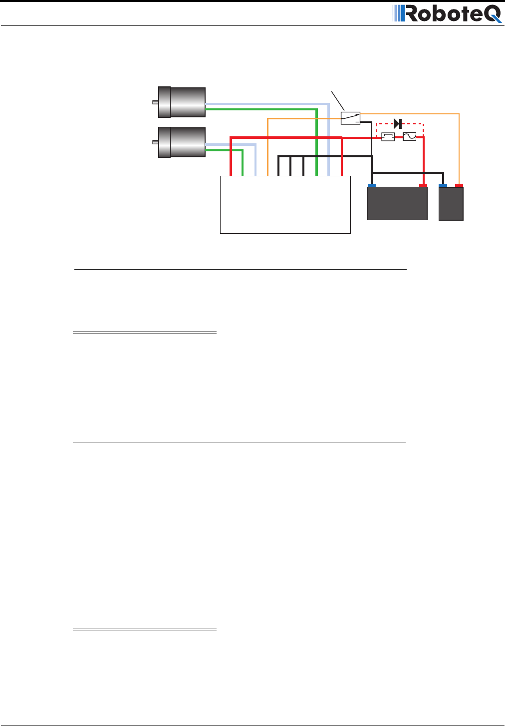
12V to 40V
Motor Battery
Power switch
On
Off
-
-
+
+
Motor1
Motor2
Controller
VMot
VMot
M1-
M1+
PwrCtrl
GND
GND
GND
M2+
M2-
12V to 40V
Backup Battery
FIGURE 10. Powering the AX1500 with a Main and Backup Supply