


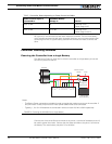
Connecting Power and Motors to the Controller
28 AX1500 Motor Controller User’s Manual Version 1.9b. June 1, 2007
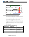
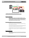
Controller Power
The AX1500 uses a flexible power supply scheme that is best described in Figure 8. In this
diagram, it can be seen that the power for the Controller’s microcomputer is separate from
this of the motor drivers. The microcomputer circuit is connected to a DC/DC converter
which takes power from either the Power Control wire or the VMot input. The diode circuit
is designed to automatically select one power source over the other, letting through the
source that is higher than the other.
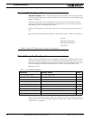
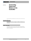
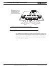
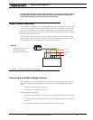
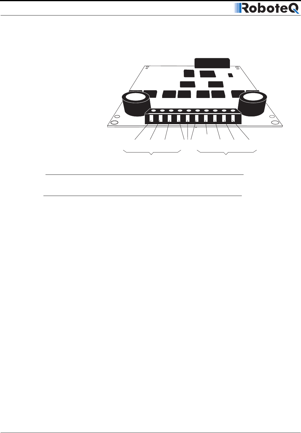
FIGURE 7. Controller Rear View and Power Connector Tabs
VMot
Motor 2 Motor 1
M2+ M1+ M1- VMotM2- 3 x Gnd
Pwr
Ctrl
Note:
Both VMot terminals are
connected to each other in
the board and must be
wired to the same voltage.