


Installing, Connecting and Using the Encoder Mod-
70 AX1500 Motor Controller User’s Manual Version 1.9b. June 1, 2007
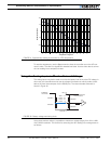
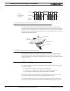
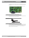
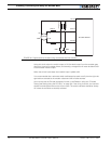
2- Carefully insert the encoder module on top of the two headers present on the control-
ler’s main board and shown in Figure 38. Beware that the two matting connectors are pre-
cisely aligned.
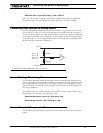
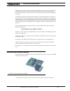
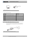
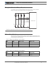
3- The encoder module will be held in place by the headers and connectors. For use in
harsh shock and vibration environments, solder a metal wire inside the 0.1” hole found on
the main board (next to one of the two header) and solder the other en inside the matching
hole on the encoder module, as shown on Figure 39.
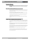
Connecting the Encoder
The Encoder module uses a widely available 8-pin RJ45 connector identical to those found
on all Ethernet devices. The connector provides 5V power to the encoders and has inputs
for the two quadrature signals from each encoder. Using multi-level signaling, it is also pos-
sible to share the quadrature inputs with limit switches. The figure and table below
describe the connector and its pin assignment.
FIGURE 38. Position of Encoder Module on Controller’s main board
Solder wire
Encoder Module
Main Board
FIGURE 39. Solder wire for robust assembly