


AX1500 Motor Controller User’s Manual 75
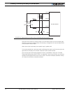
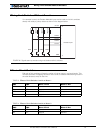
Wiring Limit Switches Without Encoders
Wiring Limit Switches Without Encoders
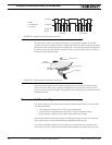
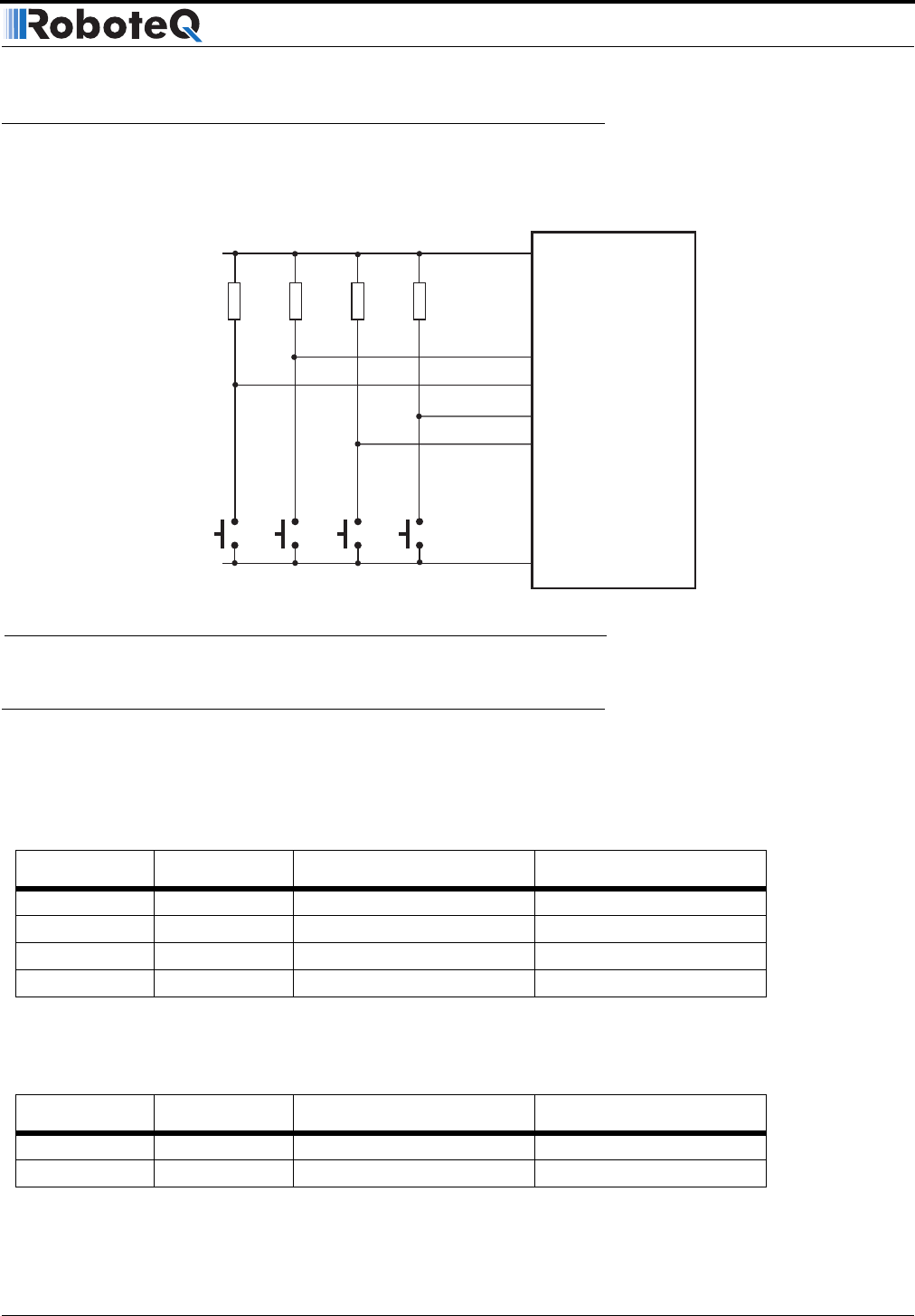
If no encoder is used, the Encoder Module’s inputs can be used to wire limit switches
directly with solely a pull-up resistor as shown in the diagram below.
Effect of Limit Switches
Each pair of limit switches will stop the motion of a given motor in a given direction. This
will have the effect of stopping the motor when a limit is reached while allowing motion in
the other direction, away for that limit.
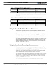
TABLE 13. Effects of Limit Switches 1 and 2 on Motor 1
SW1 SW2 Motor 1 Fwd Motor 1 Rev
OFF OFF Allowed Allowed
ON OFF Stopped Allowed
OFF ON Allowed Stopped
ON ON Stopped Stopped
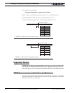
TABLE 14. Effects of Limit Switches 3 and 4 on Motor 2
SW3 SW4 Motor 2 Fwd Motor 2 Rev
OFF OFF Allowed Allowed
ON OFF Stopped Allowed
SW3
SW4
Encoder Input
GND
5V Out
Ch B In
Ch B In
Ch A In
6
1
2
5
8 - 4
7 - 3
Ch A In
4.7kOhm
4.7kOhm
SW1
SW2
4.7kOhm
4.7kOhm
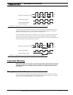
FIGURE 45. Signals seen by encoder using multi-levels and limit switches